US7797836B2 - Compact utility knife - Google Patents
Compact utility knife Download PDFInfo
- Publication number
- US7797836B2 US7797836B2 US11/194,479 US19447905A US7797836B2 US 7797836 B2 US7797836 B2 US 7797836B2 US 19447905 A US19447905 A US 19447905A US 7797836 B2 US7797836 B2 US 7797836B2
- Authority
- US
- United States
- Prior art keywords
- blade
- blade holder
- knife
- handle
- lock
- Prior art date
- Legal status (The legal status is an assumption and is not a legal conclusion. Google has not performed a legal analysis and makes no representation as to the accuracy of the status listed.)
- Active, expires
Links
Images


Classifications
-
- B—PERFORMING OPERATIONS; TRANSPORTING
- B26—HAND CUTTING TOOLS; CUTTING; SEVERING
- B26B—HAND-HELD CUTTING TOOLS NOT OTHERWISE PROVIDED FOR
- B26B5/00—Hand knives with one or more detachable blades
- B26B5/001—Hand knives with one or more detachable blades with blades being slid out of handle immediately prior to use
-
- B—PERFORMING OPERATIONS; TRANSPORTING
- B26—HAND CUTTING TOOLS; CUTTING; SEVERING
- B26B—HAND-HELD CUTTING TOOLS NOT OTHERWISE PROVIDED FOR
- B26B1/00—Hand knives with adjustable blade; Pocket knives
- B26B1/08—Hand knives with adjustable blade; Pocket knives with sliding blade
-
- B—PERFORMING OPERATIONS; TRANSPORTING
- B26—HAND CUTTING TOOLS; CUTTING; SEVERING
- B26B—HAND-HELD CUTTING TOOLS NOT OTHERWISE PROVIDED FOR
- B26B5/00—Hand knives with one or more detachable blades
- B26B5/006—Hand knives with one or more detachable blades specially adapted for using razor blades as blades
Definitions
- This invention relates to utility knives that utilize trapezoidal utility blades and can selectively expose or protect a cutting edge of the blade.
- a conventional utility knife includes a long handle with a blade holder slidably disposed within the handle. See, e.g., U.S. Pat. Nos. 4,242,795, 6,249,975.
- a trapezoidal utility blade detachably mounts to the blade holder.
- the standard trapezoidal blade has a cutting edge disposed on its longest edge and one or more mounting notches disposed on an opposite edge. When the blade holder is in a retracted position, the blade is disposed within and protected by the handle. When the blade holder is slid into an extended position, a small portion of the blade becomes exposed.
- the conventional handle is relatively long so as to provide enough longitudinal space for a user's hand to apply sufficient leverage to the blade during a cutting action, and/or to enable the user to grip the handle without being overly close to the blade's cutting edge.
- the length and size of this handle makes the utility knife large and cumbersome when the knife is not being used. Accordingly, there remains a need for a more compact utility knife that is more easily carried while not being used but is nonetheless comfortable to use when in its operative position.
- one aspect of one or more embodiments of this invention provides a utility knife that is compact when in a non-operable retracted position, and comfortably long when in an extended position.
- a knife that includes a handle and a blade holder slidingly/telescopically carried by the handle for sliding movement relative to the handle between an extended position and a retracted position.
- the blade holder is shaped and configured to attach to a trapezoidal or other type of utility blade.
- the blade holder is constructed and arranged to extend forwardly of the handle when in the extended position.
- the knife may include a trapezoidal utility blade mounted to the blade holder.
- the blade includes an elongated cutting edge that is protected by the handle when the blade holder is in the retracted position.
- the cutting edge may extend forwardly of the handle by at least 1 inch when the blade holder is in the extended position. In another embodiment, at least 40% (or more preferably at least 50%) of the cutting edge extends forwardly of the handle when the blade holder is in the extended position.
- the blade holder may be constructed and arranged to extend forwardly of the handle by at least 0.25 inches when in the extended position.
- a retracted length of the knife when the blade holder is in the retracted position is preferably less than 4.5 inches, and may be between 3.9 and 4.9 inches.
- An extended length of the knife (including a utility blade) when the blade holder is in the extended position is preferably at least 15% longer than a retracted length of the knife when the blade holder is in the retracted position.
- the extended length is more preferably at least 20% longer than the retracted length.
- the extended length is even more preferably at least 25% longer than the retracted length.
- the sliding movement between the handle and blade holder may define a curved or non-linear path.
- the curve may have a fixed radius.
- the curve may generally follow an overall shape of the handle.
- the handle may include an aperture through which the blade holder extends when in the extended position. In one or more embodiments, no portion of the blade holder extends through the aperture when the blade holder is in the retracted position.
- the knife may further include a manually operable slide lock that selectively maintains the blade holder in the retracted or extended position.
- the slide lock may also include an intermediate locking position.
- the slide lock may include a resilient member having first and second spaced portions, the first portion being mounted to the blade holder.
- the slide lock may further include a push button disposed on the resilient member. When the blade handle is locked in the extended or retracted position, manually pushing the button against a biasing force of the resilient member disengages the slide lock to allow the blade handle to slide relative to the handle.
- the knife may further include a manually operable blade lock disposed on the blade holder.
- the blade lock is manually movable from a locked position, in which the lock retains the blade in the blade holder, to a released position that allows the blade to be manually disengaged from the blade holder.
- the blade lock may include a resilient member having first and second portions, the first portion being mounted to the blade holder.
- the blade lock may also include a protrusion disposed on the second portion, the protrusion engaging a notch in an upper edge of the blade.
- the resilient member resiliently biases the protrusion downwardly toward the blade.
- a grip portion may be disposed on the resilient member.
- the blade lock may be inaccessible when the blade holder is in the retracted position.
- the protrusion may extend forwardly of the handle when the blade holder is in the extended position.
- the blade holder may have an upper edge that extends through an aperture in the handle when the blade holder is in the extended position. According to a further aspect of one or more embodiments of the present invention, the blade holder does not extend through the aperture when the blade holder is in the retracted position.
- a knife that includes a handle having an aperture therein.
- the knife also includes a blade holder slidingly carried by the handle for sliding movement relative to the handle between an extended position and a retracted position.
- the knife also includes a utility blade attached to the blade holder.
- the utility blade has a cutting edge and extends out of the aperture when the blade holder is in the extended position.
- the utility blade does not extend out of the aperture when the blade holder is in the retracted position.
- the cutting edge remains spaced from the perimeter of the aperture by at least 1 mm or at least 2 mm when the blade holder is in the extended position.
- the blade may have lateral surfaces that re spaced from lateral edges of the aperture by at least 1 mm or at least 2 mm when the blade holder is in the extended position.
- the aperture may be at least 2 mm, at least 3 mm, at least 4 mm, or at least 5 mm wide at a point on the utility blade disposed 6 mm above the cutting edge when the blade holder is in the extended position.
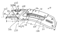
- FIG. 1 is a left side view of a utility knife according to an embodiment of the present invention in an extended position
- FIG. 2 is a left side view of the utility knife in FIG. 1 in a retracted position
- FIG. 3 is an exploded view of the utility knife in FIG. 1 ;
- FIG. 4 is a top view of the utility knife in FIG. 1 ;
- FIG. 5 is a left side view of a blade holder of the utility knife in FIG. 1 ;
- FIG. 6 is a front view of the utility knife in FIG. 1 .
- FIGS. 1-6 illustrate a compact utility knife 10 according to an embodiment of the present invention.
- the knife 10 includes a handle 20 , a blade holder 30 slidingly connected to the handle 20 , a slide lock mechanism 40 for selectively retaining the blade holder 30 in an extended position ( FIG. 1 ) or a retracted position ( FIG. 2 ), a trapezoidal utility blade 50 detachably mounted to the blade holder 30 , and a blade lock mechanism 60 for selectively locking the blade 50 onto the blade holder 30 .
- a forward direction extends to the left of knife 10 (i.e., toward a cutting end of the knife 10 ). Up and down are defined as shown in FIG. 1 .
- the handle 20 comprises left and right portions 20 a , 20 b that are screwed or otherwise fastened together.
- a U-shaped cover 70 mounts to an upper edge of the handle portions 20 a , 20 b via screws or other fastening mechanisms.
- a belt clip 80 is screwed or otherwise fastened to the right handle portion 20 b . While the illustrated handle 20 comprises a variety of components, one or more of these components may be omitted without deviating from the scope of the present invention.
- the blade holder 30 comprises left and right holder portions 30 a , 30 b that are fastened to each other using rivets 100 or other suitable fastening mechanisms (e.g., screws, integral formation, glue, welding, etc.).
- the blade holder comprises a single, integrally formed member rather than two members secured together.
- the handle 20 and blade holder 30 include cooperating surface features 20 c , 30 c that define a sliding/telescopic path of the blade holder 30 .
- the surface features 20 c , 30 c comprise mating channels and surfaces.
- the upper and lower surface features 30 c of the blade holder 30 slidingly engage internal surfaces 20 c within the handle 20 .
- the sliding/telescopic path is a fixed radius curved path having a center of curvature disposed below the knife 10 . Accordingly, a forward tip of the blade 50 angles progressively more downwardly as the blade holder 30 slides from its retracted position to its extended position.
- the path may alternatively comprise any other suitable shape (e.g., a linear or non-linear shape, a convex or concave curve, a variable radius curve, etc.) without deviating from the scope of the present invention.
- suitable shape e.g., a linear or non-linear shape, a convex or concave curve, a variable radius curve, etc.
- the blade holder 30 telescopically extends out of an aperture 20 d in the handle 20 .
- the aperture 20 d has a contiguous perimeter, but may alternatively have an open perimeter (e.g., an open slot), without deviating from the scope of the present invention.
- both upper and lower edges 30 d , 30 e of the blade holder 30 extend out of the aperture 20 d when the blade holder 30 is in the extended position.
- no portion of the blade holder 30 extends out of the aperture 20 d when the blade holder 30 is in the retracted position.
- the blade holder 30 extends out of the aperture 20 d even when the blade holder 30 is in the retracted position.
- the aperture 20 d creates a significant gap between the blade 50 and the handle 20 . Accordingly, if foreign debris (e.g., sap, tar, glue, adhesive, etc.) accumulates on the blade 50 during use, the gap provides sufficient clearance to reduce the likelihood that such debris will transfer to the handle 20 when the blade 50 is retracted and subsequently extended. Conversely, when the blade 50 is in the retracted position, the handle 20 encloses the blade 50 to discourage any foreign debris on the blade 50 from transferring to other objects (e.g., a person's pocket, other tools in a toolbox, etc.).
- other objects e.g., a person's pocket, other tools in a toolbox, etc.
- the blade 50 is preferably centrally disposed in the aperture 20 d , but may be offset in any direction without departing from the scope of the present invention.
- the aperture 20 d may be at least twice as wide as the blade 50 .
- the aperture 20 d may be at least 3, 4, 5, 6, 8, 10, or 15 times wider than the blade 50 .
- the aperture 20 d is between 3 and 15 times wider than the blade 50 .
- the lateral sides 50 c of the blade 50 preferably remain spaced from the perimeter of the aperture 20 d by a distance that is at least 1 mm, and may be at least 2 mm, at least 3 mm, or at least 4 mm.
- the lateral sides of the blade 50 are spaced from the lateral sides of the aperture 20 d by between 1 mm and 5 mm.
- the cutting edge 50 a may be spaced from the perimeter of the aperture 20 d by a cutting edge gap that is at least 1 mm as the blade 50 retracts from the extended to the retracted position.
- the cutting edge gap may be at least 2 mm, at least 3 mm, or at least 4 mm. In one embodiment, the cutting edge gap is between 1 and 5 mm.
- a width W of the aperture 20 d is preferably large enough to create a gap between the lateral sides of the blade 50 and the lateral sides of the aperture 20 d .
- the width W may be between 1 and 10 mm.
- the width W may be between 2 and 11 mm.
- the width W may be between 3 and 10 mm.
- the width W may be greater than 1 mm, greater than 2 mm, greater than 3 mm, or greater than 4 mm. In one embodiment, the width W is about 5.3 mm.
- a width W′ of the aperture 20 d is defined at a point 300 on the utility blade 50 disposed 6 mm above the cutting edge 50 a (i.e., a point on the blade 50 that is spaced from the cutting edge 50 a by 6 mm in a direction perpendicular to the linear cutting edge 50 a ).
- the width W′ may be greater than 2 mm, greater than 3 mm, or greater than 4 mm. In one embodiment, the width W′ is between 3 and 10 mm. In one embodiment, the width W′ is about 5.3 mm.
- the width W may vary over its height.
- the width W is smaller toward an upper edge of the blade 50 , and relatively larger toward the cutting edge 50 a of the blade 50 .
- a portion of the aperture 20 d that is disposed adjacent to an upper half of the utility blade 50 is narrower than a portion of the aperture 20 d that is disposed adjacent the lower half of the utility blade 50 .
- the lower halves of the lateral surfaces 50 c of the utility blade 50 i.e., portions of the lateral surfaces 50 c that are disposed below an imaginary line that is parallel to and equally spaced from the upper and lower edges of the blade 50 ) are spaced from the lateral edges of the aperture 20 d by at least 1 mm when the utility blade 50 is in the extended position.
- the lower halves of the lateral surfaces 50 c may be spaced from the lateral edges of the aperture 20 d by at least 2 mm or at least 3 mm when the utility blade 50 is in the extended position.
- the upper portions of the lateral surfaces 50 c may be disposed closer to the lateral edges of the aperture 20 d .
- the narrower upper portion of the aperture 20 d may enable the handle 20 to laterally support the blade 50 , while the relatively wider lower portion of the aperture 20 d reduces the likelihood that debris will transfer from the blade 50 to the handle 20 when the blade 50 slides to its retracted position.
- an enlarged aperture 20 d is shown in connection with a utility knife 10 that includes a blade carrier 30 that extends forward of the handle 20
- an enlarged aperture according to the present invention may alternatively be incorporated into various conventional utility knives.
- a utility knife according to the present invention need not include an enlarged aperture 20 d .
- the gap formed by the aperture 20 d may be eliminated without deviating from the scope of the present invention.
- the aperture 20 d may scrape against the sides 50 c , top, and/or cutting edge 50 a of the blade 50 as the blade 50 extends and retracts. Such scraping may scrape debris from the blade 50 when the blade 50 is retracted and/or provide lateral support to the extended blade 50 .
- an overall longitudinal shape of the handle 30 generally mimics the sliding path.
- a resulting curvature of the handle 20 makes it more comfortable to grip.
- the slide lock mechanism 40 comprises a resilient member 130 constructed and arranged to be mounted at one end to the blade holder 30 .
- the resilient member 130 has openings 131 that enable the resilient member 130 to be fastened to the blade holder 30 by use of two of the rivets 100 that fasten the blade holder portions 30 a , 30 b together.
- a projection 140 extends laterally outwardly from an opposite end of the resilient member 130 to define a push button 145 . As shown in FIGS. 1 and 3 , the projection 140 and push button 145 extend outwardly through a slot 150 in the handle 20 .
- the slot 150 generally mimics the sliding path of the blade holder 30 .
- An upper surface of the slot 150 includes forward and rearward notches 150 a , 150 b .
- the resilient member 130 urges the projection 140 upwardly toward the notches 150 a , 150 b .
- the projection 140 engages the notch 150 a to retain the blade holder 30 in the extended position.
- the projection 140 engages the notch 150 b to retain the blade holder 30 in the fully retracted position.
- a user depresses the button 145 downwardly and/or inwardly against the biasing force of the resilient member 130 to disengage the projection 140 from the notch 150 a or 150 b .
- the user then pushes the button 145 in a forward or rearward direction to extend or retract the blade holder 30 and blade 50 .
- the projection 140 engages the corresponding notch 150 a , 150 b to lock the blade holder 30 in the new position.
- additional notches may be formed in the slot 150 to provide additional locking positions for the blade holder 30 (e.g., a partially extended/intermediate position in which only a small portion of the blade 50 extends out of the handle 20 , a hyper-extended position, etc.).
- the extended and retracted positions of the blade holder 30 are the fully extended and fully retracted positions of the blade holder 30 . It is nonetheless contemplated that the blade holder 30 could extend or retract beyond these positions without deviating from the scope of the present invention.
- the blade 50 comprises a standard trapezoidal utility blade having an elongated cutting edge 50 a disposed on its lower edge. Two mounting notches 50 b are disposed on an upper edge of the blade 50 . The upper shorter edge is not sharpened.
- the blade 50 can be formed in a conventional process as known in the art. While the illustrated knife 10 uses a trapezoidal blade 50 , any other suitable utility blade may be used instead of a trapezoidal blade without deviating from the scope of the present invention. For example, a knife according to the present invention may be designed for use with a rectangular utility blade.
- the blade lock mechanism 60 comprises a resilient member 200 mounted at one end to the blade holder 30 .
- the resilient member 200 has a plurality of openings 202 that enable the lock mechanism 60 to be fastened to the blade holder 30 using two of the rivets 100 that fasten the blade holder portions 30 a , 30 b together.
- a protrusion/detent 210 extends downwardly from a forward portion of the resilient member 200 .
- the resilient member 200 biases the protrusion 210 downwardly.
- a grip portion 220 provides an exterior grip surface disposed on the forward portion of the resilient member 200 .
- the protrusion 210 engages a notch 50 b of the blade 50 to retain the blade 50 in the blade holder 30 .
- the blade 50 may be detached from the blade holder 30 by manually lifting the grip portion 220 against the biasing force of the resilient member 200 until the protrusion 210 disengages from the notch 50 b .
- the blade 50 may then be manually moved forwardly out of the blade holder 30 .
- the resilient member 200 , protrusion 210 , and grip portion 220 are all integrally formed from a unitary sheet material. However, these components may alternatively be separately formed and subsequently connected to each other without deviating from the scope of the present invention.
- the blade lock mechanism 60 is only accessible when the blade holder 30 is in the extended position.
- the blade lock mechanism 60 is disposed at least partially within the handle 20 so as to prevent the blade lock mechanism 60 from releasing the blade 50 when the knife 50 is not being used.
- the blade lock mechanism 60 can be accessed when retracted, but cannot be moved to release the blade 50 .
- the blade lock mechanism 60 can both be accessed and used to release the blade 50 whether retracted or extended.
- the illustrated resilient members 130 , 200 preferably comprise a strong, elastically deformable material such as spring steel that is stamped and bent to form the resilient members 130 , 200 .
- the resilient member 130 , 200 may alternatively comprise any other suitable material or composite of materials and may be formed in any other suitable manner without deviating from the scope of the present invention.
- slide lock and blade lock mechanisms 40 , 60 are illustrated, any other suitable selective locking mechanism may alternatively be used without deviating from the scope of the present invention.
- the utility knife 10 is compact when in the retracted position and comfortably long when in the extended position.
- the blade holder 30 extends forwardly of the handle 20 by a distance h when in the extended position.
- the distance h may be at least 0.25 inches, or more preferably at least 0.5 inches. In one embodiment, the distance h is between 0.7 inches and 1.0 inches, an preferably about 0.85 inches. In one embodiment, the distance h is between 0.5 and 2 inches.
- the blade 50 extends forwardly of the handle 20 by a distance b when the blade holder 30 is in the extended position.
- the distance b may be at least 0.75 inches, or more preferably at least 1 inch, or more preferably at least 1.25 inches.
- the distance b is between 1.2 and 1.6 inches, and preferably about 1.45 inches.
- the distance b may be between 1 and 3 inches.
- the distance b is preferably at least 40% of the length of the cutting edge 50 a , is more preferably at least 50% of the length of the cutting edge 50 a , and is even more preferably greater than or about 60% of the length of the cutting edge 50 a , such that the blade 50 extends significantly forwardly from the handle 20 .
- the distance b could be larger than the length of the cutting edge 50 a such that the blade 50 is disposed entirely forward of the handle 20 .
- the distances b, h are measured from a plane 250 that is tangent to a forwardmost point on the handle 20 and is perpendicular to an axis 260 defined by the cutting edge 50 a.
- the protrusion 210 of the blade lock 60 also extends forwardly of the handle 20 when the blade holder 30 is in the extended position. Accordingly, the blade lock 60 is easily accessible when the blade holder 30 is in the extended position.
- an overall extended length e of the knife 10 is defined as the largest distance between any two points on the knife 10 (including the blade 50 ).
- a overall retracted length r of the knife 10 is defined in the same manner.
- the length e is preferably between 5 and 7 inches, and even more preferably less than 6.0 inches. In one embodiment, the length e is about 5.7 inches.
- the length r is preferably less than 5 inches, and may be less than 4.5 inches.
- the length r is preferably between 3.9 and 4.9 inches. In one embodiment, the length r is about 4.3 inches.
- the length e is preferably at least 15% larger than the length r (i.e., a ratio e:r is at least 1.15:1).
- the length e is more preferably at least 20% larger than the length r, is even more preferably at least 25% larger than the length r, and is even more preferably at least 30% larger than the length r. In one embodiment, the length e is about 33% larger than the length r. Accordingly, the knife 10 is substantially longer in its operative position than it is in its retracted position, making the knife 10 comfortable to use and easy to store/carry.
- the distance h is preferably at least 5% of the distance r, is more preferably at least 10% of the distance r, and is even more preferably at least 15% of the distance r. In the illustrated embodiment, the distance h is approximately 20% of the distance r such that extending the blade holder 30 significantly extends an overall length of the knife 10 .
- the knife 10 may also include a blade storage compartment for storing replacement blade(s) 50 .
Abstract
Description
Claims (80)
Priority Applications (5)
| Application Number | Priority Date | Filing Date | Title |
|---|---|---|---|
| US11/194,479 US7797836B2 (en) | 2005-08-02 | 2005-08-02 | Compact utility knife |
| FR0607039A FR2892334B1 (en) | 2005-08-02 | 2006-08-01 | MULTIPLE PURPOSE COMPACT SHAPE TRANCH. |
| GB0615280A GB2428618B (en) | 2005-08-02 | 2006-08-01 | A knife |
| US12/423,551 US7930829B2 (en) | 2005-08-02 | 2009-04-14 | Compact utility knife |
| US13/050,662 US8549755B2 (en) | 2005-08-02 | 2011-03-17 | Compact utility knife |
Applications Claiming Priority (1)
| Application Number | Priority Date | Filing Date | Title |
|---|---|---|---|
| US11/194,479 US7797836B2 (en) | 2005-08-02 | 2005-08-02 | Compact utility knife |
Related Parent Applications (1)
| Application Number | Title | Priority Date | Filing Date |
|---|---|---|---|
| US11/194,448 Continuation US7520059B2 (en) | 2005-08-02 | 2005-08-02 | Compact utility knife |
Related Child Applications (1)
| Application Number | Title | Priority Date | Filing Date |
|---|---|---|---|
| US12/423,551 Continuation US7930829B2 (en) | 2005-08-02 | 2009-04-14 | Compact utility knife |
Publications (3)
| Publication Number | Publication Date |
|---|---|
| US20070028455A1 US20070028455A1 (en) | 2007-02-08 |
| US20080282546A2 US20080282546A2 (en) | 2008-11-20 |
| US7797836B2 true US7797836B2 (en) | 2010-09-21 |
Family
ID=37006563
Family Applications (3)
| Application Number | Title | Priority Date | Filing Date |
|---|---|---|---|
| US11/194,479 Active 2027-02-02 US7797836B2 (en) | 2005-08-02 | 2005-08-02 | Compact utility knife |
| US12/423,551 Active US7930829B2 (en) | 2005-08-02 | 2009-04-14 | Compact utility knife |
| US13/050,662 Active US8549755B2 (en) | 2005-08-02 | 2011-03-17 | Compact utility knife |
Family Applications After (2)
| Application Number | Title | Priority Date | Filing Date |
|---|---|---|---|
| US12/423,551 Active US7930829B2 (en) | 2005-08-02 | 2009-04-14 | Compact utility knife |
| US13/050,662 Active US8549755B2 (en) | 2005-08-02 | 2011-03-17 | Compact utility knife |
Country Status (3)
| Country | Link |
|---|---|
| US (3) | US7797836B2 (en) |
| FR (1) | FR2892334B1 (en) |
| GB (1) | GB2428618B (en) |
Cited By (17)
| Publication number | Priority date | Publication date | Assignee | Title |
|---|---|---|---|---|
| US20090204135A1 (en) * | 2008-02-07 | 2009-08-13 | Becton, Dickinson And Company | Retractable safety knife |
| US20100154224A1 (en) * | 2008-12-22 | 2010-06-24 | Meridian International Co., Ltd. | Novel sliding cutting tool |
| US20110162212A1 (en) * | 2005-08-02 | 2011-07-07 | Stanley Black & Decker, Inc. | Compact utility knife |
| WO2012154867A2 (en) * | 2011-05-09 | 2012-11-15 | Olympia Tools International, Inc. | Utility knife with cut-out blade holder and extended blade guard |
| US20140150268A1 (en) * | 2012-07-04 | 2014-06-05 | Harry S. Billado, JR. | Utility Knife |
| US9174347B2 (en) | 2012-03-23 | 2015-11-03 | Meridian International Co., Ltd. | Retractable utility knife |
| USD749929S1 (en) | 2014-12-29 | 2016-02-23 | Js Products, Inc. | Utility knife handle |
| USD749928S1 (en) | 2014-12-29 | 2016-02-23 | Js Products, Inc. | Utility knife handle |
| USD769693S1 (en) * | 2015-06-16 | 2016-10-25 | Milwaukee Electric Tool Corporation | Utility knife |
| USD769692S1 (en) * | 2015-06-16 | 2016-10-25 | Milwaukee Electric Tool Corporation | Utility knife |
| US9676106B2 (en) | 2008-04-29 | 2017-06-13 | Pacific Handy Cutter, Inc. | Safety cutter with guard-actuated blade deployment |
| US9840013B2 (en) | 2008-04-29 | 2017-12-12 | Pacific Handy Cutter, Inc. | Safety cutter with blade change/storage mechanism |
| US10144139B2 (en) | 2015-04-02 | 2018-12-04 | Milwaukee Electric Tool Corporation | Utility knife |
| USD881667S1 (en) * | 2018-06-08 | 2020-04-21 | Wen-Ke Han | Folding knife |
| USD897809S1 (en) * | 2019-01-02 | 2020-10-06 | Zhejiang Xingda Stationery Co. Ltd. | Utility knife |
| USD897808S1 (en) * | 2019-01-02 | 2020-10-06 | Zhejiang Xingda Stationery Co. Ltd. | Utility knife |
| US11154380B2 (en) | 2017-10-26 | 2021-10-26 | King Abdulaziz University | Dental restoration scalpel |
Families Citing this family (38)
| Publication number | Priority date | Publication date | Assignee | Title |
|---|---|---|---|---|
| DD216908A1 (en) * | 1983-07-22 | 1985-01-02 | Horst Spiegel | FOURDERER FOR PACKAGING MACHINES |
| US7909826B2 (en) * | 2005-03-24 | 2011-03-22 | Depuy Spine, Inc. | Low profile spinal tethering methods |
| US7520059B2 (en) * | 2005-08-02 | 2009-04-21 | The Stanley Works | Compact utility knife |
| TWM310093U (en) * | 2006-08-31 | 2007-04-21 | Kantas Products Co Ltd | Cutter with changeable blades |
| US9221092B2 (en) | 2006-09-01 | 2015-12-29 | Standard Lifters, Inc. | Guided keeper assembly and method for metal forming dies |
| US8006389B2 (en) | 2007-05-21 | 2011-08-30 | Pacific Handy Cutter, Inc. | Pocket safety cutter |
| US20100299935A1 (en) * | 2007-11-26 | 2010-12-02 | Great Neck Saw Manufacturers, Inc. | Folding utility knife |
| DE102008019441A1 (en) * | 2008-04-17 | 2009-10-22 | Martor Kg | knife |
| US7797835B2 (en) * | 2008-02-07 | 2010-09-21 | Min Zheng Zeng | Foldable knife with disposable blades |
| US20090199409A1 (en) * | 2008-02-07 | 2009-08-13 | Min Zheng Zeng | Foldable Knife with Disposable Blades |
| US20090241345A1 (en) * | 2008-03-26 | 2009-10-01 | Yin Han Huang | Utility knife with a pivotal actuator served as an auxiliary handgrip |
| US8201336B2 (en) | 2008-05-02 | 2012-06-19 | Olympia Tools International, Inc. | Retractable utility knife |
| US8695221B2 (en) | 2008-08-21 | 2014-04-15 | Wen Hao | Utility knife with extended travel carriage |
| US20100223793A1 (en) * | 2009-03-04 | 2010-09-09 | The Stanley Works | Utility knife |
| US8307556B2 (en) * | 2009-06-19 | 2012-11-13 | ADCO Industries—Technologies, L.P. | Utility cutter |
| US20110197454A1 (en) * | 2010-02-17 | 2011-08-18 | Zeng min-zheng | Cutter |
| CN202011027U (en) * | 2011-01-18 | 2011-10-19 | 吴劲松 | Novel paper cutter |
| GB2505383A (en) * | 2011-06-22 | 2014-02-26 | Yuewei Wu | A retractable telescoping utility knife |
| US20130061475A1 (en) * | 2011-09-08 | 2013-03-14 | Joseph L. Lutgen | Ergonomic Cutter |
| US9314935B2 (en) * | 2011-12-22 | 2016-04-19 | Ken Everett | Floor groover |
| WO2014000347A1 (en) * | 2012-06-28 | 2014-01-03 | 杭州巨星工具有限公司 | Utility knife |
| US8769826B2 (en) * | 2012-07-11 | 2014-07-08 | Yuewei Wu | Cutting device |
| US9550302B2 (en) * | 2012-12-21 | 2017-01-24 | Stanley Black & Decker, Inc. | Utility knife with blade wiper |
| US10468152B2 (en) * | 2013-02-21 | 2019-11-05 | Global Graphene Group, Inc. | Highly conducting and transparent film and process for producing same |
| USD738182S1 (en) * | 2013-05-31 | 2015-09-08 | Irwin Industrial Tool Company | Utility knife |
| USD742716S1 (en) * | 2013-05-31 | 2015-11-10 | Irwin Industrial Tool Company | Utility knife handle |
| USD732367S1 (en) * | 2013-05-31 | 2015-06-23 | Irwin Industrial Tool Company | Utility knife handle |
| US20180250837A1 (en) * | 2015-06-17 | 2018-09-06 | Starrett Indústria E Comércio Ltda | Improvements made to a compact safety cutter |
| EP3165336A1 (en) | 2015-11-04 | 2017-05-10 | Stanley Black & Decker, Inc. | Spring assisted utility knife |
| EP3165337B1 (en) | 2015-11-05 | 2020-03-18 | Stanley Black & Decker, Inc. | Utility knife with skewed pivotal blade lock |
| USD843807S1 (en) * | 2016-06-03 | 2019-03-26 | Browning | Folding knife |
| USD793836S1 (en) * | 2016-06-09 | 2017-08-08 | Browning | Foldable knife |
| DE102019119612A1 (en) | 2019-07-19 | 2021-01-21 | Wolfcraft Gmbh | Safety knife |
| USD920074S1 (en) * | 2020-01-17 | 2021-05-25 | Coast Cutlery Co. | Knife |
| USD986022S1 (en) * | 2021-01-28 | 2023-05-16 | Zonghong Li | Utility knife |
| USD994455S1 (en) * | 2021-08-16 | 2023-08-08 | Apex Brands, Inc. | Utility knife |
| USD1017372S1 (en) * | 2022-06-01 | 2024-03-12 | Yuewei Wu | Utility knife |
| USD1017371S1 (en) * | 2022-07-05 | 2024-03-12 | Yuewei Wu | Utility knife |
Citations (117)
| Publication number | Priority date | Publication date | Assignee | Title |
|---|---|---|---|---|
| US493075A (en) | 1892-09-17 | 1893-03-07 | Razor | |
| US515045A (en) | 1894-02-20 | Pocket-knife | ||
| US705441A (en) * | 1902-03-15 | 1902-07-22 | Newton Ezra Putney | Knife. |
| US1444324A (en) | 1919-03-24 | 1923-02-06 | Percy C Brooks | Cutting implement |
| US1496927A (en) * | 1923-01-24 | 1924-06-10 | William A Evers | Razor-blade holder |
| US1500550A (en) | 1921-09-15 | 1924-07-08 | D Hondt Louis | Eraser |
| US1706251A (en) | 1927-07-29 | 1929-03-19 | Perry Edmund Stephen | Knife |
| US1753441A (en) * | 1929-03-27 | 1930-04-08 | Morehouse Frank | Screw driver |
| US1940855A (en) | 1931-06-25 | 1933-12-26 | Friedman Hugo | Knife |
| US2051721A (en) | 1935-06-03 | 1936-08-18 | George N Kirangelos | Knife |
| US2134973A (en) | 1938-01-29 | 1938-11-01 | Wilbur F Harwell | Knife |
| US2265775A (en) | 1939-12-09 | 1941-12-09 | Leon R Mcnamara | Pocketknife |
| US2284128A (en) | 1939-05-12 | 1942-05-26 | Paine L Bush | Tool and blade holder |
| US2523575A (en) | 1947-04-14 | 1950-09-26 | Morris B Kassel | Cutting device |
| US2569080A (en) * | 1949-02-24 | 1951-09-25 | Trimble Ernest | Knife using a detachable razor blade |
| US2599439A (en) * | 1950-07-31 | 1952-06-03 | Howard T Drake | Sheathed razor blade holder |
| US2601723A (en) * | 1947-12-15 | 1952-07-01 | Cedarberg Mfg Company Inc | Scraper employing razor blade |
| US2632244A (en) * | 1949-02-16 | 1953-03-24 | Belsky Charles | Toolholder |
| US2735176A (en) | 1956-02-21 | Veterinary surgical knife | ||
| US2914850A (en) | 1957-10-24 | 1959-12-01 | Eversharp Inc | Razor blade knife |
| US2980966A (en) | 1958-09-29 | 1961-04-25 | Nat Broach & Mach | Method of molding a gear finishing tool |
| US3192624A (en) * | 1963-10-30 | 1965-07-06 | Allway Mfg Co Inc | Knife handle with adjustable blade |
| US3234649A (en) | 1964-03-13 | 1966-02-15 | Gen Slicing Machine Co Inc | Twin-blade releasing means |
| US3306297A (en) | 1964-06-01 | 1967-02-28 | Sel Mar Inc | Tracheotomy set |
| US3708881A (en) * | 1971-03-22 | 1973-01-09 | R Bennett | Multi position adjustable roofing knife |
| US3845554A (en) | 1973-04-19 | 1974-11-05 | N Joanis | Knife blade and handle |
| US3879847A (en) * | 1973-05-11 | 1975-04-29 | Smart Ag | Cutter with forwardly and rearwardly displaceable blade |
| CA972140A (en) | 1973-01-08 | 1975-08-05 | Robert A. Bennett | Multi position adjustable roofing knife |
| US3927473A (en) | 1974-04-18 | 1975-12-23 | Philip Morris Inc | Replaceable blade knife |
| US3943627A (en) | 1973-11-28 | 1976-03-16 | Stanley Jr Conrad | Front loading utility knife |
| US3964162A (en) * | 1975-06-25 | 1976-06-22 | Louis M. Gerson Co., Inc. | Blade scraper |
| US3999290A (en) | 1976-03-15 | 1976-12-28 | Wood Jess W | Safety knife |
| US4017969A (en) | 1976-04-20 | 1977-04-19 | Stonebraker Robert E | Cutting instrument |
| US4109380A (en) | 1977-07-05 | 1978-08-29 | Anderson Lloyd E | Cutting tool and blade holder for replaceable blades |
| US4242795A (en) | 1979-02-02 | 1981-01-06 | The Stanley Works | Knife handle |
| US4261104A (en) | 1979-06-29 | 1981-04-14 | Cuscovitch John F | Holder for detachable blades |
| US4265017A (en) | 1979-09-07 | 1981-05-05 | Jenkins Metal Corporation | Pocket knife with retractable blade |
| US4347665A (en) | 1981-05-11 | 1982-09-07 | Glesser Louis S | Pocket knife |
| US4408396A (en) * | 1982-03-15 | 1983-10-11 | Scholl Albert S | Trim knife |
| US4517741A (en) | 1982-05-19 | 1985-05-21 | Castelluzzo James M | Knife with plural replaceable blade storage and means for single blade extension |
| US4558517A (en) | 1983-11-30 | 1985-12-17 | Donald Gringer | Scraper hand tool |
| US4575940A (en) | 1980-07-25 | 1986-03-18 | Wenzel Michael D | Replaceable blade knife |
| US4586256A (en) | 1985-01-07 | 1986-05-06 | The Stanley Works | Knife handle |
| US4604805A (en) | 1983-12-14 | 1986-08-12 | John F. Cuscovitch | Holder for detachable blades |
| US4620369A (en) | 1984-08-09 | 1986-11-04 | Gercken Richard H | Drywall knife |
| US4635309A (en) * | 1985-05-17 | 1987-01-13 | Larsen Peter L | Multiple use hand tool |
| US4660284A (en) | 1985-07-17 | 1987-04-28 | The Stanley Works | Folding pocket saw |
| US4663845A (en) | 1986-03-05 | 1987-05-12 | Stanley Tools | Utility knife |
| US4761882A (en) | 1986-02-18 | 1988-08-09 | Hunt X-Acto, Inc. | Utility knife |
| US4805304A (en) | 1986-07-03 | 1989-02-21 | D. G. S. Research & Development | Utility knife having a sliding blade holder |
| US4813132A (en) | 1986-08-08 | 1989-03-21 | James Castelluzzo | Utility knife |
| US4835865A (en) | 1986-07-03 | 1989-06-06 | Martor-Argentax E.H. Beermann Kg | Hollow-handle utility knife replaceable blade |
| US4899443A (en) * | 1987-10-31 | 1990-02-13 | Martor-Argentax E.H. Beermann Kg | Safety knife for cardboard and like materials |
| US4936014A (en) | 1989-04-06 | 1990-06-26 | Johnson Level And Tool (Canada) Inc. | Utility knife |
| US5095624A (en) | 1990-12-07 | 1992-03-17 | Ennis Raynold W | Lock system for a folding knife |
| US5203085A (en) | 1992-01-02 | 1993-04-20 | Martor-Argentax E.H. Beermann Kg | Knife |
| US5207696A (en) | 1992-04-30 | 1993-05-04 | Medical Sterile Products, Inc. | Surgical scalpel |
| US5303469A (en) | 1993-04-15 | 1994-04-19 | Yin Han Huang | Cutter knife |
| WO1994015762A1 (en) | 1993-01-12 | 1994-07-21 | Pacific Handy Cutter, Inc. | Ergonomic utility knife/box cutter and method of making |
| US5344424A (en) | 1993-03-12 | 1994-09-06 | Roberts Philip L | Selectively retractable, disposable surgical knife |
| GB2277048A (en) | 1993-04-14 | 1994-10-19 | Yin Han Huang | Cutting tool with detachable blade |
| US5384963A (en) | 1993-03-27 | 1995-01-31 | Martor-Argentax E. H. Beermann Kg | Razor knife with autoretracting blade |
| US5400512A (en) | 1994-03-01 | 1995-03-28 | Brush; Jerry L. | Windshield molding removing knife |
| US5406707A (en) | 1994-01-21 | 1995-04-18 | The Stanley Works | Utility knife with improved slide |
| US5571127A (en) | 1995-03-08 | 1996-11-05 | Decampli; William M. | Scalpel handle having retractable blade support and method of use |
| US5749886A (en) | 1993-06-18 | 1998-05-12 | Leonard Bloom | Disposable guarded finger scalpel for inserting a line in a patient and blade therefor |
| DE29819618U1 (en) | 1998-11-03 | 1999-01-21 | Chen Chun Chiung | knife |
| US5864954A (en) | 1997-09-02 | 1999-02-02 | Harrington Tools, Inc. | Slitter tool |
| US5878501A (en) | 1997-08-08 | 1999-03-09 | The Stanley Works | Utility knife with retractable blade guard |
| US5890293A (en) | 1995-09-21 | 1999-04-06 | Gamba; Gregory G. | Cutting tool having blade holder assembly |
| US5909930A (en) | 1997-08-05 | 1999-06-08 | Millers Falls Tool Company | Retractable blade utility knife having quick change feature |
| US5966816A (en) | 1998-11-20 | 1999-10-19 | Roberson; Robbie E. | Straight knife with interchangeable pivoting blade |
| US5966817A (en) | 1998-02-23 | 1999-10-19 | Lee; Tze-Ming | Art designer blade device |
| US6026575A (en) | 1997-11-14 | 2000-02-22 | American Safety Razor Company | Utility knife handle |
| US6148520A (en) * | 1997-06-04 | 2000-11-21 | Martor-Argentax E.H. Beermann Kg | Box cutter with autoretracting blade |
| US6192589B1 (en) * | 1999-06-25 | 2001-02-27 | The Stanley Works | Utility knife |
| US6249975B1 (en) | 1999-12-20 | 2001-06-26 | Hsing Tai Lin | Blade support device for a knife |
| US6263581B1 (en) | 1998-03-19 | 2001-07-24 | Philip Forte | Hunting knife with removable blade edges |
| US6286215B1 (en) * | 1999-06-14 | 2001-09-11 | Hyde Manufacturing Company | Retractable blade scraper |
| US6314646B1 (en) * | 1999-12-15 | 2001-11-13 | Pacific Handy Cutter, Inc. | Utility knife |
| US6354007B1 (en) | 2000-09-29 | 2002-03-12 | Robert E. Scarla | Utility knife |
| US6374497B1 (en) | 2001-07-09 | 2002-04-23 | Taiwan San Tyau Co., Ltd. | Utility cutter |
| US20020096032A1 (en) | 2000-11-24 | 2002-07-25 | Jean-Claude Peyrot | Cutter with monoblock blade carrier with securement and release of the blade by pressure |
| US6446340B1 (en) | 2000-11-14 | 2002-09-10 | Great Neck Saw Manufacturers, Inc. | Utility knife |
| US20030037444A1 (en) * | 2001-08-21 | 2003-02-27 | Chunn Steve Howard | Ergonomically shaped, fixed blade, front loading utility knife with extra blades storage compartment having single blade retrieval system |
| US6543140B1 (en) | 2000-07-05 | 2003-04-08 | Adco Industries | Utility knife having improved blade carrier structure and method of manufacture thereof |
| US6550144B1 (en) * | 1999-04-09 | 2003-04-22 | Harald Berns | Hollow-handle razor knife with blade slide |
| US20030079294A1 (en) | 2001-10-31 | 2003-05-01 | Van Deursen Gary E. | Combination utility and sporting knife |
| EP0893211B1 (en) | 1997-07-25 | 2003-07-23 | MARTOR-ARGENTAX E.H. Beermann KG | Knife |
| US20030150116A1 (en) | 2000-09-29 | 2003-08-14 | Robert Scala | Utility knife blade securing device |
| US20030154605A1 (en) | 2002-02-13 | 2003-08-21 | Chien-Chuan Chao | Craft knife having interchangeable blades |
| US6645216B2 (en) * | 2002-02-14 | 2003-11-11 | David H. Masury | Surgical scalpel |
| US6688003B2 (en) * | 2000-09-29 | 2004-02-10 | Robert E. Scarla | Utility knife |
| EP1422031A1 (en) | 2002-11-19 | 2004-05-26 | Spellbound Development Group | Safety Cutting Apparatus |
| US6742260B1 (en) | 2003-02-26 | 2004-06-01 | Cheng-Hui Hsu | Structure art design knife |
| US20040107580A1 (en) | 2002-12-10 | 2004-06-10 | Great Neck Saw Manufacturers, Inc. | Utility knife |
| DE20308706U1 (en) | 2003-06-04 | 2004-06-24 | Martor Kg | Craft knife has interchangeable blade held between two housing parts forming handle which has inside a rocker arm with two lever arms for clamping and releasing blade |
| US6757977B2 (en) | 2001-11-20 | 2004-07-06 | Jai Surgicals Limited | Disposable surgical safety scalpel |
| US20040139614A1 (en) | 2003-01-17 | 2004-07-22 | Tebo Glenn J. | Utility knife |
| US6775912B2 (en) * | 2002-01-24 | 2004-08-17 | A. Richard Ltée | Blade scraping tool |
| US6796033B2 (en) | 2002-02-11 | 2004-09-28 | Greg J. Owoc | Utility knife |
| US20050055833A1 (en) | 2000-09-29 | 2005-03-17 | Scarla Robert E. | Pivoting securing device for a utility knife blade |
| US6907668B2 (en) | 2003-05-22 | 2005-06-21 | Martor Kg | Utility knife |
| US20050188541A1 (en) | 2003-11-10 | 2005-09-01 | Brown Donald A. | Utility knife with actuator for moving blade carrier and for releasing blade therefrom, and related method |
| US6948250B1 (en) | 2003-03-06 | 2005-09-27 | Caiafa Jr Gerard | Retractable/disposable craft knife and blade insert therefor |
| US6968622B2 (en) * | 2003-05-13 | 2005-11-29 | Great Neck Saw Manufacturers, Inc. | Utility knife |
| US7003833B2 (en) * | 2004-02-11 | 2006-02-28 | Pedro Feliciano | Hand-held carpenters tool |
| US20060130340A1 (en) | 2004-12-22 | 2006-06-22 | Harald Berns | Knife |
| US20060130339A1 (en) | 2004-12-22 | 2006-06-22 | Harald Berns | Knife |
| US7134207B2 (en) * | 2003-05-13 | 2006-11-14 | Great Neck Saw Manufacturers, Inc. | Foldable utility knife |
| US20070028455A1 (en) | 2005-08-02 | 2007-02-08 | The Stanley Works | Compact utility knife |
| US20070119056A1 (en) | 2005-11-29 | 2007-05-31 | Martor Kg | Utility knife |
| US20080189956A1 (en) | 2005-10-13 | 2008-08-14 | Gudula Polei | Knife |
| US7475480B2 (en) | 2004-04-05 | 2009-01-13 | The Votolato Living Trust | Disposable blade cartridge utility knife |
| US7520059B2 (en) | 2005-08-02 | 2009-04-21 | The Stanley Works | Compact utility knife |
| US7540092B2 (en) | 2005-10-24 | 2009-06-02 | Martor Kg | Utility knife |
| US20090271990A1 (en) | 2008-05-02 | 2009-11-05 | Huang Yuan De | Retractable utility knife |
Family Cites Families (10)
| Publication number | Priority date | Publication date | Assignee | Title |
|---|---|---|---|---|
| US4285125A (en) * | 1979-05-14 | 1981-08-25 | Warner-Lambert Company | Barber-type razor |
| NL9201371A (en) * | 1992-07-29 | 1994-02-16 | Emerson Electric Co | Saw blade fixing device. |
| US5787501A (en) * | 1997-03-21 | 1998-08-04 | Trace Athletic Corporation | Hand and wrist protector for in-line skating |
| FR2780908B1 (en) * | 1998-07-10 | 2000-09-29 | Genus Technologies | POSITIONING AND CENTERING DEVICE |
| US6779425B2 (en) * | 2000-11-27 | 2004-08-24 | Ctech Ag | Multipurpose handheld implement |
| US6285215B1 (en) * | 1999-09-02 | 2001-09-04 | Micron Technology, Inc. | Output driver having a programmable edge rate |
| US20060272157A1 (en) | 2005-06-07 | 2006-12-07 | Zeng Min Z | Foldable knife |
| US8695221B2 (en) * | 2008-08-21 | 2014-04-15 | Wen Hao | Utility knife with extended travel carriage |
| US20100223793A1 (en) * | 2009-03-04 | 2010-09-09 | The Stanley Works | Utility knife |
| US20110197454A1 (en) * | 2010-02-17 | 2011-08-18 | Zeng min-zheng | Cutter |
-
2005
- 2005-08-02 US US11/194,479 patent/US7797836B2/en active Active
-
2006
- 2006-08-01 GB GB0615280A patent/GB2428618B/en active Active
- 2006-08-01 FR FR0607039A patent/FR2892334B1/en not_active Expired - Fee Related
-
2009
- 2009-04-14 US US12/423,551 patent/US7930829B2/en active Active
-
2011
- 2011-03-17 US US13/050,662 patent/US8549755B2/en active Active
Patent Citations (120)
| Publication number | Priority date | Publication date | Assignee | Title |
|---|---|---|---|---|
| US515045A (en) | 1894-02-20 | Pocket-knife | ||
| US2735176A (en) | 1956-02-21 | Veterinary surgical knife | ||
| US493075A (en) | 1892-09-17 | 1893-03-07 | Razor | |
| US705441A (en) * | 1902-03-15 | 1902-07-22 | Newton Ezra Putney | Knife. |
| US1444324A (en) | 1919-03-24 | 1923-02-06 | Percy C Brooks | Cutting implement |
| US1500550A (en) | 1921-09-15 | 1924-07-08 | D Hondt Louis | Eraser |
| US1496927A (en) * | 1923-01-24 | 1924-06-10 | William A Evers | Razor-blade holder |
| US1706251A (en) | 1927-07-29 | 1929-03-19 | Perry Edmund Stephen | Knife |
| US1753441A (en) * | 1929-03-27 | 1930-04-08 | Morehouse Frank | Screw driver |
| US1940855A (en) | 1931-06-25 | 1933-12-26 | Friedman Hugo | Knife |
| US2051721A (en) | 1935-06-03 | 1936-08-18 | George N Kirangelos | Knife |
| US2134973A (en) | 1938-01-29 | 1938-11-01 | Wilbur F Harwell | Knife |
| US2284128A (en) | 1939-05-12 | 1942-05-26 | Paine L Bush | Tool and blade holder |
| US2265775A (en) | 1939-12-09 | 1941-12-09 | Leon R Mcnamara | Pocketknife |
| US2523575A (en) | 1947-04-14 | 1950-09-26 | Morris B Kassel | Cutting device |
| US2601723A (en) * | 1947-12-15 | 1952-07-01 | Cedarberg Mfg Company Inc | Scraper employing razor blade |
| US2632244A (en) * | 1949-02-16 | 1953-03-24 | Belsky Charles | Toolholder |
| US2569080A (en) * | 1949-02-24 | 1951-09-25 | Trimble Ernest | Knife using a detachable razor blade |
| US2599439A (en) * | 1950-07-31 | 1952-06-03 | Howard T Drake | Sheathed razor blade holder |
| US2914850A (en) | 1957-10-24 | 1959-12-01 | Eversharp Inc | Razor blade knife |
| US2980966A (en) | 1958-09-29 | 1961-04-25 | Nat Broach & Mach | Method of molding a gear finishing tool |
| US3192624A (en) * | 1963-10-30 | 1965-07-06 | Allway Mfg Co Inc | Knife handle with adjustable blade |
| US3234649A (en) | 1964-03-13 | 1966-02-15 | Gen Slicing Machine Co Inc | Twin-blade releasing means |
| US3306297A (en) | 1964-06-01 | 1967-02-28 | Sel Mar Inc | Tracheotomy set |
| US3708881A (en) * | 1971-03-22 | 1973-01-09 | R Bennett | Multi position adjustable roofing knife |
| CA972140A (en) | 1973-01-08 | 1975-08-05 | Robert A. Bennett | Multi position adjustable roofing knife |
| US3845554A (en) | 1973-04-19 | 1974-11-05 | N Joanis | Knife blade and handle |
| US3879847A (en) * | 1973-05-11 | 1975-04-29 | Smart Ag | Cutter with forwardly and rearwardly displaceable blade |
| US3943627A (en) | 1973-11-28 | 1976-03-16 | Stanley Jr Conrad | Front loading utility knife |
| US3927473A (en) | 1974-04-18 | 1975-12-23 | Philip Morris Inc | Replaceable blade knife |
| US3964162A (en) * | 1975-06-25 | 1976-06-22 | Louis M. Gerson Co., Inc. | Blade scraper |
| US3999290A (en) | 1976-03-15 | 1976-12-28 | Wood Jess W | Safety knife |
| US4017969A (en) | 1976-04-20 | 1977-04-19 | Stonebraker Robert E | Cutting instrument |
| US4109380A (en) | 1977-07-05 | 1978-08-29 | Anderson Lloyd E | Cutting tool and blade holder for replaceable blades |
| US4242795A (en) | 1979-02-02 | 1981-01-06 | The Stanley Works | Knife handle |
| US4261104A (en) | 1979-06-29 | 1981-04-14 | Cuscovitch John F | Holder for detachable blades |
| US4265017A (en) | 1979-09-07 | 1981-05-05 | Jenkins Metal Corporation | Pocket knife with retractable blade |
| US4575940A (en) | 1980-07-25 | 1986-03-18 | Wenzel Michael D | Replaceable blade knife |
| US4347665A (en) | 1981-05-11 | 1982-09-07 | Glesser Louis S | Pocket knife |
| US4408396A (en) * | 1982-03-15 | 1983-10-11 | Scholl Albert S | Trim knife |
| US4517741A (en) | 1982-05-19 | 1985-05-21 | Castelluzzo James M | Knife with plural replaceable blade storage and means for single blade extension |
| US4517741B1 (en) | 1982-05-19 | 1988-12-27 | ||
| US4558517A (en) | 1983-11-30 | 1985-12-17 | Donald Gringer | Scraper hand tool |
| US4604805A (en) | 1983-12-14 | 1986-08-12 | John F. Cuscovitch | Holder for detachable blades |
| US4620369A (en) | 1984-08-09 | 1986-11-04 | Gercken Richard H | Drywall knife |
| US4586256A (en) | 1985-01-07 | 1986-05-06 | The Stanley Works | Knife handle |
| US4635309A (en) * | 1985-05-17 | 1987-01-13 | Larsen Peter L | Multiple use hand tool |
| US4660284A (en) | 1985-07-17 | 1987-04-28 | The Stanley Works | Folding pocket saw |
| US4761882A (en) | 1986-02-18 | 1988-08-09 | Hunt X-Acto, Inc. | Utility knife |
| US4663845A (en) | 1986-03-05 | 1987-05-12 | Stanley Tools | Utility knife |
| US4805304A (en) | 1986-07-03 | 1989-02-21 | D. G. S. Research & Development | Utility knife having a sliding blade holder |
| US4835865A (en) | 1986-07-03 | 1989-06-06 | Martor-Argentax E.H. Beermann Kg | Hollow-handle utility knife replaceable blade |
| US4813132A (en) | 1986-08-08 | 1989-03-21 | James Castelluzzo | Utility knife |
| US4899443A (en) * | 1987-10-31 | 1990-02-13 | Martor-Argentax E.H. Beermann Kg | Safety knife for cardboard and like materials |
| US4936014A (en) | 1989-04-06 | 1990-06-26 | Johnson Level And Tool (Canada) Inc. | Utility knife |
| US5095624A (en) | 1990-12-07 | 1992-03-17 | Ennis Raynold W | Lock system for a folding knife |
| US5203085A (en) | 1992-01-02 | 1993-04-20 | Martor-Argentax E.H. Beermann Kg | Knife |
| US5207696A (en) | 1992-04-30 | 1993-05-04 | Medical Sterile Products, Inc. | Surgical scalpel |
| WO1994015762A1 (en) | 1993-01-12 | 1994-07-21 | Pacific Handy Cutter, Inc. | Ergonomic utility knife/box cutter and method of making |
| US5344424A (en) | 1993-03-12 | 1994-09-06 | Roberts Philip L | Selectively retractable, disposable surgical knife |
| US5384963A (en) | 1993-03-27 | 1995-01-31 | Martor-Argentax E. H. Beermann Kg | Razor knife with autoretracting blade |
| GB2277048A (en) | 1993-04-14 | 1994-10-19 | Yin Han Huang | Cutting tool with detachable blade |
| US5303469A (en) | 1993-04-15 | 1994-04-19 | Yin Han Huang | Cutter knife |
| US5749886A (en) | 1993-06-18 | 1998-05-12 | Leonard Bloom | Disposable guarded finger scalpel for inserting a line in a patient and blade therefor |
| US5406707A (en) | 1994-01-21 | 1995-04-18 | The Stanley Works | Utility knife with improved slide |
| US5400512A (en) | 1994-03-01 | 1995-03-28 | Brush; Jerry L. | Windshield molding removing knife |
| US5571127A (en) | 1995-03-08 | 1996-11-05 | Decampli; William M. | Scalpel handle having retractable blade support and method of use |
| US5890293A (en) | 1995-09-21 | 1999-04-06 | Gamba; Gregory G. | Cutting tool having blade holder assembly |
| US6148520A (en) * | 1997-06-04 | 2000-11-21 | Martor-Argentax E.H. Beermann Kg | Box cutter with autoretracting blade |
| EP0893211B1 (en) | 1997-07-25 | 2003-07-23 | MARTOR-ARGENTAX E.H. Beermann KG | Knife |
| US5909930A (en) | 1997-08-05 | 1999-06-08 | Millers Falls Tool Company | Retractable blade utility knife having quick change feature |
| US5878501A (en) | 1997-08-08 | 1999-03-09 | The Stanley Works | Utility knife with retractable blade guard |
| US5864954A (en) | 1997-09-02 | 1999-02-02 | Harrington Tools, Inc. | Slitter tool |
| US6026575A (en) | 1997-11-14 | 2000-02-22 | American Safety Razor Company | Utility knife handle |
| US5966817A (en) | 1998-02-23 | 1999-10-19 | Lee; Tze-Ming | Art designer blade device |
| US6263581B1 (en) | 1998-03-19 | 2001-07-24 | Philip Forte | Hunting knife with removable blade edges |
| DE29819618U1 (en) | 1998-11-03 | 1999-01-21 | Chen Chun Chiung | knife |
| US5966816A (en) | 1998-11-20 | 1999-10-19 | Roberson; Robbie E. | Straight knife with interchangeable pivoting blade |
| US6550144B1 (en) * | 1999-04-09 | 2003-04-22 | Harald Berns | Hollow-handle razor knife with blade slide |
| US6286215B1 (en) * | 1999-06-14 | 2001-09-11 | Hyde Manufacturing Company | Retractable blade scraper |
| US6192589B1 (en) * | 1999-06-25 | 2001-02-27 | The Stanley Works | Utility knife |
| US6314646B1 (en) * | 1999-12-15 | 2001-11-13 | Pacific Handy Cutter, Inc. | Utility knife |
| US6249975B1 (en) | 1999-12-20 | 2001-06-26 | Hsing Tai Lin | Blade support device for a knife |
| US6543140B1 (en) | 2000-07-05 | 2003-04-08 | Adco Industries | Utility knife having improved blade carrier structure and method of manufacture thereof |
| US20030150116A1 (en) | 2000-09-29 | 2003-08-14 | Robert Scala | Utility knife blade securing device |
| US6354007B1 (en) | 2000-09-29 | 2002-03-12 | Robert E. Scarla | Utility knife |
| US6915577B2 (en) * | 2000-09-29 | 2005-07-12 | Robert Scala | Utility knife blade securing device |
| US20050055833A1 (en) | 2000-09-29 | 2005-03-17 | Scarla Robert E. | Pivoting securing device for a utility knife blade |
| US6688003B2 (en) * | 2000-09-29 | 2004-02-10 | Robert E. Scarla | Utility knife |
| US6446340B1 (en) | 2000-11-14 | 2002-09-10 | Great Neck Saw Manufacturers, Inc. | Utility knife |
| US20020096032A1 (en) | 2000-11-24 | 2002-07-25 | Jean-Claude Peyrot | Cutter with monoblock blade carrier with securement and release of the blade by pressure |
| US6374497B1 (en) | 2001-07-09 | 2002-04-23 | Taiwan San Tyau Co., Ltd. | Utility cutter |
| US20030037444A1 (en) * | 2001-08-21 | 2003-02-27 | Chunn Steve Howard | Ergonomically shaped, fixed blade, front loading utility knife with extra blades storage compartment having single blade retrieval system |
| US20030079294A1 (en) | 2001-10-31 | 2003-05-01 | Van Deursen Gary E. | Combination utility and sporting knife |
| US6757977B2 (en) | 2001-11-20 | 2004-07-06 | Jai Surgicals Limited | Disposable surgical safety scalpel |
| US6775912B2 (en) * | 2002-01-24 | 2004-08-17 | A. Richard Ltée | Blade scraping tool |
| US6796033B2 (en) | 2002-02-11 | 2004-09-28 | Greg J. Owoc | Utility knife |
| US20030154605A1 (en) | 2002-02-13 | 2003-08-21 | Chien-Chuan Chao | Craft knife having interchangeable blades |
| US6645216B2 (en) * | 2002-02-14 | 2003-11-11 | David H. Masury | Surgical scalpel |
| EP1422031A1 (en) | 2002-11-19 | 2004-05-26 | Spellbound Development Group | Safety Cutting Apparatus |
| US20040107580A1 (en) | 2002-12-10 | 2004-06-10 | Great Neck Saw Manufacturers, Inc. | Utility knife |
| US20040139614A1 (en) | 2003-01-17 | 2004-07-22 | Tebo Glenn J. | Utility knife |
| US6742260B1 (en) | 2003-02-26 | 2004-06-01 | Cheng-Hui Hsu | Structure art design knife |
| US6948250B1 (en) | 2003-03-06 | 2005-09-27 | Caiafa Jr Gerard | Retractable/disposable craft knife and blade insert therefor |
| US6968622B2 (en) * | 2003-05-13 | 2005-11-29 | Great Neck Saw Manufacturers, Inc. | Utility knife |
| US7134207B2 (en) * | 2003-05-13 | 2006-11-14 | Great Neck Saw Manufacturers, Inc. | Foldable utility knife |
| US6907668B2 (en) | 2003-05-22 | 2005-06-21 | Martor Kg | Utility knife |
| DE20308706U1 (en) | 2003-06-04 | 2004-06-24 | Martor Kg | Craft knife has interchangeable blade held between two housing parts forming handle which has inside a rocker arm with two lever arms for clamping and releasing blade |
| US20050188541A1 (en) | 2003-11-10 | 2005-09-01 | Brown Donald A. | Utility knife with actuator for moving blade carrier and for releasing blade therefrom, and related method |
| US7003833B2 (en) * | 2004-02-11 | 2006-02-28 | Pedro Feliciano | Hand-held carpenters tool |
| US7475480B2 (en) | 2004-04-05 | 2009-01-13 | The Votolato Living Trust | Disposable blade cartridge utility knife |
| US20060130339A1 (en) | 2004-12-22 | 2006-06-22 | Harald Berns | Knife |
| US20060130340A1 (en) | 2004-12-22 | 2006-06-22 | Harald Berns | Knife |
| US20070028455A1 (en) | 2005-08-02 | 2007-02-08 | The Stanley Works | Compact utility knife |
| US7520059B2 (en) | 2005-08-02 | 2009-04-21 | The Stanley Works | Compact utility knife |
| US20090193665A1 (en) | 2005-08-02 | 2009-08-06 | The Stanley Works | Compact utility knife |
| US20080189956A1 (en) | 2005-10-13 | 2008-08-14 | Gudula Polei | Knife |
| US7540092B2 (en) | 2005-10-24 | 2009-06-02 | Martor Kg | Utility knife |
| US20070119056A1 (en) | 2005-11-29 | 2007-05-31 | Martor Kg | Utility knife |
| US20090271990A1 (en) | 2008-05-02 | 2009-11-05 | Huang Yuan De | Retractable utility knife |
Non-Patent Citations (15)
| Title |
|---|
| Examination Report issued for Great Britain Patent Application No. 0615280.5, dated May 29, 2009. |
| Martor Catalog (95 pages). |
| Martor IM chat: Alleged Apr. 21, 2009 "Chat With Martor Customer Service". (3 pages). |
| Mator USA Online, Trapezoidal Blades, http://www.martorusa.com/Blades/Trapezoid-Blades?range=1%2C25%2C34, Accessed on Jun. 24, 2010. * |
| Mator USA Online, Trapezoidal Blades, Saved on Mar. 30, 2004, http://web.archive.org/web/20030308063534/martorusa.com/cart/products.asp?grouping-id=19, Accessed on Jun. 24, 2010. * |
| Mator USA Online, Trapezoidal Blades, Saved on Mar. 30, 2004, http://web.archive.org/web/20030308063534/martorusa.com/cart/products.asp?grouping—id=19, Accessed on Jun. 24, 2010. * |
| Megasafe Poster(2 pages). |
| Optisafe Poster (2 pages). |
| Photographs of Martor Maxisafe KNife and Box (4 pages). |
| Photographs of Martor Megasafe Knife and Box (6 pages). |
| Photographs of Martor Optisafe Knife and Box (6 pages) |
| Photographs of Pacific Handy Cutter S3 Knife and Box (5 pages). |
| Six alleged photographs of Martor knives (6 pages). |
| U.S. Office Action dated Nov. 9, 2009 for U.S. Appl. No. 12/423,551. |
| United Kingdom Search Report issued for Patent Application No. GB0615280.5, dated Oct. 25. 2006. |
Cited By (27)
| Publication number | Priority date | Publication date | Assignee | Title |
|---|---|---|---|---|
| US20110162212A1 (en) * | 2005-08-02 | 2011-07-07 | Stanley Black & Decker, Inc. | Compact utility knife |
| US8549755B2 (en) | 2005-08-02 | 2013-10-08 | Stanley Black & Decker, Inc. | Compact utility knife |
| US8464430B2 (en) * | 2008-02-07 | 2013-06-18 | Beaver-Visitec International (Us), Inc. | Retractable safety knife |
| US20090204135A1 (en) * | 2008-02-07 | 2009-08-13 | Becton, Dickinson And Company | Retractable safety knife |
| US9840013B2 (en) | 2008-04-29 | 2017-12-12 | Pacific Handy Cutter, Inc. | Safety cutter with blade change/storage mechanism |
| US9676106B2 (en) | 2008-04-29 | 2017-06-13 | Pacific Handy Cutter, Inc. | Safety cutter with guard-actuated blade deployment |
| US8028420B2 (en) * | 2008-12-22 | 2011-10-04 | Meridian International Co., Ltd. | Sliding cutting tool |
| US20100154224A1 (en) * | 2008-12-22 | 2010-06-24 | Meridian International Co., Ltd. | Novel sliding cutting tool |
| WO2012154867A2 (en) * | 2011-05-09 | 2012-11-15 | Olympia Tools International, Inc. | Utility knife with cut-out blade holder and extended blade guard |
| WO2012154867A3 (en) * | 2011-05-09 | 2013-03-07 | Olympia Tools International, Inc. | Utility knife with cut-out blade holder and extended blade guard |
| US9370869B2 (en) | 2012-03-23 | 2016-06-21 | Meridian International Co., Ltd. | Retractable utility knife |
| US9174347B2 (en) | 2012-03-23 | 2015-11-03 | Meridian International Co., Ltd. | Retractable utility knife |
| US20140150268A1 (en) * | 2012-07-04 | 2014-06-05 | Harry S. Billado, JR. | Utility Knife |
| US20160039101A1 (en) * | 2012-07-04 | 2016-02-11 | Harry S. Billado, JR. | Utility Knife |
| US9108323B2 (en) * | 2012-07-04 | 2015-08-18 | Gbh Products, Llc | Utility knife |
| USD749928S1 (en) | 2014-12-29 | 2016-02-23 | Js Products, Inc. | Utility knife handle |
| USD749929S1 (en) | 2014-12-29 | 2016-02-23 | Js Products, Inc. | Utility knife handle |
| US11724408B2 (en) | 2015-04-02 | 2023-08-15 | Milwaukee Electric Tool Corporation | Utility knife |
| US10144139B2 (en) | 2015-04-02 | 2018-12-04 | Milwaukee Electric Tool Corporation | Utility knife |
| USD769693S1 (en) * | 2015-06-16 | 2016-10-25 | Milwaukee Electric Tool Corporation | Utility knife |
| USD769692S1 (en) * | 2015-06-16 | 2016-10-25 | Milwaukee Electric Tool Corporation | Utility knife |
| US11154380B2 (en) | 2017-10-26 | 2021-10-26 | King Abdulaziz University | Dental restoration scalpel |
| US11219504B1 (en) | 2017-10-26 | 2022-01-11 | King Abdulaziz University | Dental cosmetic scalpel |
| US11219503B2 (en) | 2017-10-26 | 2022-01-11 | King Abdulaziz University | Method for contouring a dental restoration |
| USD881667S1 (en) * | 2018-06-08 | 2020-04-21 | Wen-Ke Han | Folding knife |
| USD897809S1 (en) * | 2019-01-02 | 2020-10-06 | Zhejiang Xingda Stationery Co. Ltd. | Utility knife |
| USD897808S1 (en) * | 2019-01-02 | 2020-10-06 | Zhejiang Xingda Stationery Co. Ltd. | Utility knife |
Also Published As
| Publication number | Publication date |
|---|---|
| US20070028455A1 (en) | 2007-02-08 |
| GB2428618A (en) | 2007-02-07 |
| US20110162212A1 (en) | 2011-07-07 |
| US20080282546A2 (en) | 2008-11-20 |
| GB2428618B (en) | 2010-02-24 |
| US8549755B2 (en) | 2013-10-08 |
| US7930829B2 (en) | 2011-04-26 |
| FR2892334B1 (en) | 2019-07-05 |
| US20090193665A1 (en) | 2009-08-06 |
| GB0615280D0 (en) | 2006-09-06 |
| FR2892334A1 (en) | 2007-04-27 |
Similar Documents
| Publication | Publication Date | Title |
|---|---|---|
| US7797836B2 (en) | Compact utility knife | |
| US7520059B2 (en) | Compact utility knife | |
| US11571824B2 (en) | Utility knife | |
| US10252428B2 (en) | Utility knife with skewed pivotal blade lock | |
| US7316070B2 (en) | Self-retracting utility knife | |
| US9370869B2 (en) | Retractable utility knife | |
| US10349664B2 (en) | Skinning knife with removable blade | |
| CA2683881C (en) | Dual front utility knife with interlock | |
| US8291598B2 (en) | Retractable blade scraper having a blade-storage drawer and a blade slide with upper and lower blade-clamping members | |
| US20100281696A1 (en) | Self loading utility knife | |
| US20060150423A1 (en) | Adjustable blade utility knife | |
| US20090277016A1 (en) | Utility knife with an auto-retractable blade | |
| US20090235533A1 (en) | Utility knife with a fixed blade and a self-retracting blade | |
| US20070068001A1 (en) | Folding tool with lock | |
| US20140208596A1 (en) | Sliding Blade Knife | |
| US20170120463A1 (en) | Spring-assisted utility knife | |
| US11554511B2 (en) | Safety knife with slidable grip | |
| US11607818B1 (en) | Pocket knife | |
| US11639006B1 (en) | Pocket knife | |
| CA2631792A1 (en) | A utility knife with an auto-retractable blade |
Legal Events
| Date | Code | Title | Description |
|---|---|---|---|
| AS | Assignment |
Owner name: STANLEY WORKS, THE, CONNECTICUT Free format text: ASSIGNMENT OF ASSIGNORS INTEREST;ASSIGNORS:RANIERI, ERIC;ROWLAY, STEPHEN;VAN DEURSEN, GARY E.;SIGNING DATES FROM 20050719 TO 20050720;REEL/FRAME:017909/0080 Owner name: STANLEY WORKS, THE, CONNECTICUT Free format text: ASSIGNMENT OF ASSIGNORS INTEREST;ASSIGNORS:RANIERI, ERIC;ROWLAY, STEPHEN;VAN DEURSEN, GARY E.;REEL/FRAME:017909/0080;SIGNING DATES FROM 20050719 TO 20050720 |
|
| FEPP | Fee payment procedure |
Free format text: PAYOR NUMBER ASSIGNED (ORIGINAL EVENT CODE: ASPN); ENTITY STATUS OF PATENT OWNER: LARGE ENTITY |
|
| FEPP | Fee payment procedure |
Free format text: PAYOR NUMBER ASSIGNED (ORIGINAL EVENT CODE: ASPN); ENTITY STATUS OF PATENT OWNER: LARGE ENTITY Free format text: PAYER NUMBER DE-ASSIGNED (ORIGINAL EVENT CODE: RMPN); ENTITY STATUS OF PATENT OWNER: LARGE ENTITY |
|
| STCF | Information on status: patent grant |
Free format text: PATENTED CASE |
|
| FEPP | Fee payment procedure |
Free format text: PAYOR NUMBER ASSIGNED (ORIGINAL EVENT CODE: ASPN); ENTITY STATUS OF PATENT OWNER: LARGE ENTITY Free format text: PAYER NUMBER DE-ASSIGNED (ORIGINAL EVENT CODE: RMPN); ENTITY STATUS OF PATENT OWNER: LARGE ENTITY |
|
| FPAY | Fee payment |
Year of fee payment: 4 |
|
| MAFP | Maintenance fee payment |
Free format text: PAYMENT OF MAINTENANCE FEE, 8TH YEAR, LARGE ENTITY (ORIGINAL EVENT CODE: M1552) Year of fee payment: 8 |
|
| MAFP | Maintenance fee payment |
Free format text: PAYMENT OF MAINTENANCE FEE, 12TH YEAR, LARGE ENTITY (ORIGINAL EVENT CODE: M1553); ENTITY STATUS OF PATENT OWNER: LARGE ENTITY Year of fee payment: 12 |