US5127762A - Connector assembly - Google Patents
Connector assembly Download PDFInfo
- Publication number
- US5127762A US5127762A US07/318,555 US31855589A US5127762A US 5127762 A US5127762 A US 5127762A US 31855589 A US31855589 A US 31855589A US 5127762 A US5127762 A US 5127762A
- Authority
- US
- United States
- Prior art keywords
- handle
- handle members
- connector
- housing
- members
- Prior art date
- Legal status (The legal status is an assumption and is not a legal conclusion. Google has not performed a legal analysis and makes no representation as to the accuracy of the status listed.)
- Expired - Lifetime
Links
- 239000000463 material Substances 0.000 claims abstract description 12
- 230000003014 reinforcing effect Effects 0.000 claims abstract description 6
- 238000005728 strengthening Methods 0.000 claims 1
- 230000006870 function Effects 0.000 description 4
- 239000002184 metal Substances 0.000 description 3
- 238000003306 harvesting Methods 0.000 description 2
- DHKHKXVYLBGOIT-UHFFFAOYSA-N acetaldehyde Diethyl Acetal Natural products CCOC(C)OCC DHKHKXVYLBGOIT-UHFFFAOYSA-N 0.000 description 1
- 150000001241 acetals Chemical class 0.000 description 1
- 230000008878 coupling Effects 0.000 description 1
- 238000010168 coupling process Methods 0.000 description 1
- 238000005859 coupling reaction Methods 0.000 description 1
- 230000007547 defect Effects 0.000 description 1
- 230000000994 depressogenic effect Effects 0.000 description 1
- 238000010413 gardening Methods 0.000 description 1
- 238000000034 method Methods 0.000 description 1
- 230000000717 retained effect Effects 0.000 description 1
Images

Classifications
-
- B—PERFORMING OPERATIONS; TRANSPORTING
- B62—LAND VEHICLES FOR TRAVELLING OTHERWISE THAN ON RAILS
- B62B—HAND-PROPELLED VEHICLES, e.g. HAND CARTS OR PERAMBULATORS; SLEDGES
- B62B5/00—Accessories or details specially adapted for hand carts
- B62B5/06—Hand moving equipment, e.g. handle bars
-
- F—MECHANICAL ENGINEERING; LIGHTING; HEATING; WEAPONS; BLASTING
- F16—ENGINEERING ELEMENTS AND UNITS; GENERAL MEASURES FOR PRODUCING AND MAINTAINING EFFECTIVE FUNCTIONING OF MACHINES OR INSTALLATIONS; THERMAL INSULATION IN GENERAL
- F16B—DEVICES FOR FASTENING OR SECURING CONSTRUCTIONAL ELEMENTS OR MACHINE PARTS TOGETHER, e.g. NAILS, BOLTS, CIRCLIPS, CLAMPS, CLIPS OR WEDGES; JOINTS OR JOINTING
- F16B7/00—Connections of rods or tubes, e.g. of non-circular section, mutually, including resilient connections
- F16B7/04—Clamping or clipping connections
- F16B7/0406—Clamping or clipping connections for rods or tubes being coaxial
- F16B7/0413—Clamping or clipping connections for rods or tubes being coaxial for tubes using the innerside thereof
- F16B7/042—Clamping or clipping connections for rods or tubes being coaxial for tubes using the innerside thereof with a locking element, e.g. pin, ball or pushbutton, engaging in a hole in the wall of at least one tube
-
- Y—GENERAL TAGGING OF NEW TECHNOLOGICAL DEVELOPMENTS; GENERAL TAGGING OF CROSS-SECTIONAL TECHNOLOGIES SPANNING OVER SEVERAL SECTIONS OF THE IPC; TECHNICAL SUBJECTS COVERED BY FORMER USPC CROSS-REFERENCE ART COLLECTIONS [XRACs] AND DIGESTS
- Y10—TECHNICAL SUBJECTS COVERED BY FORMER USPC
- Y10T—TECHNICAL SUBJECTS COVERED BY FORMER US CLASSIFICATION
- Y10T403/00—Joints and connections
- Y10T403/32—Articulated members
- Y10T403/32254—Lockable at fixed position
- Y10T403/32426—Plural distinct positions
- Y10T403/32442—At least one discrete position
- Y10T403/32451—Step-by-step adjustment
- Y10T403/32459—Retainer extends through aligned recesses
-
- Y—GENERAL TAGGING OF NEW TECHNOLOGICAL DEVELOPMENTS; GENERAL TAGGING OF CROSS-SECTIONAL TECHNOLOGIES SPANNING OVER SEVERAL SECTIONS OF THE IPC; TECHNICAL SUBJECTS COVERED BY FORMER USPC CROSS-REFERENCE ART COLLECTIONS [XRACs] AND DIGESTS
- Y10—TECHNICAL SUBJECTS COVERED BY FORMER USPC
- Y10T—TECHNICAL SUBJECTS COVERED BY FORMER US CLASSIFICATION
- Y10T403/00—Joints and connections
- Y10T403/55—Member ends joined by inserted section
- Y10T403/559—Fluted or splined section
-
- Y—GENERAL TAGGING OF NEW TECHNOLOGICAL DEVELOPMENTS; GENERAL TAGGING OF CROSS-SECTIONAL TECHNOLOGIES SPANNING OVER SEVERAL SECTIONS OF THE IPC; TECHNICAL SUBJECTS COVERED BY FORMER USPC CROSS-REFERENCE ART COLLECTIONS [XRACs] AND DIGESTS
- Y10—TECHNICAL SUBJECTS COVERED BY FORMER USPC
- Y10T—TECHNICAL SUBJECTS COVERED BY FORMER US CLASSIFICATION
- Y10T403/00—Joints and connections
- Y10T403/57—Distinct end coupler
-
- Y—GENERAL TAGGING OF NEW TECHNOLOGICAL DEVELOPMENTS; GENERAL TAGGING OF CROSS-SECTIONAL TECHNOLOGIES SPANNING OVER SEVERAL SECTIONS OF THE IPC; TECHNICAL SUBJECTS COVERED BY FORMER USPC CROSS-REFERENCE ART COLLECTIONS [XRACs] AND DIGESTS
- Y10—TECHNICAL SUBJECTS COVERED BY FORMER USPC
- Y10T—TECHNICAL SUBJECTS COVERED BY FORMER US CLASSIFICATION
- Y10T403/00—Joints and connections
- Y10T403/60—Biased catch or latch
- Y10T403/602—Biased catch or latch by separate spring
- Y10T403/604—Radially sliding catch
Definitions
- the present invention is related to connectors or couplings for securing together unthreaded pipe or tubular members.
- the invention has particular application to handle members for manually operated gardening and harvesting appliances which are normally propelled by hand and are supported by a pair of wheels, such as lawn mowers, drop spreaders, broadcast spreaders and the like.
- the handles for such appliances are of the knockdown type by which means the appliance can be compactly shipped from the manufacturer to the point of sale; and also, once in use by the consumer, it can be stored away in a compact space after the handle has been disassembled by the consumer.
- such handles comprise more than one piece and their ease of assembly and overall strength and durability are brought into question because of the joint portions necessary for assembly and disassembly, the joints themselves often being the weakest portion of the handle.
- the invention provides joint connections for an articulated handle so that the handle can be easily and quickly assembled or disassembled without tools and without sacrificing overall strength and durability.
- the present invention provides a connector assembly which joins two tubular handle members together so that the tubular material of the members at the joint portion is reinforced by an underlying metal sheath in one embodiment.
- the ends of the handle members overlap one another and are connected by the connector housing of the invention so that all three members overlap in a concentric relationship to thereby provide a secure joint.
- a joint connector which is adapted to have one part press-fitted with one handle member and another opposed part adapted to be slip-fitted to the other handle member.
- the press-fit portion of the connector assembly according to the invention is, however, capable of being removed from its mooring in the handle member by using more than average or normal force, such as would be required to provide a removable or slip-fit, so that if it is desired to remove the connector from both handle members, that is possible as well.
- the invention contemplates establishing the press-fit of the connector to one handle member at the factory, so that the user or operator of the appliance will only have to manipulate the removable portion of the connector in order to implement handle assembly or disassembly.
- a tubular connector of a generally rectangular cross-section comprising a housing of resilient plastic material having an agressive memory for enabling a pair of opposed tab members thereon to cooperate with respective apertures in the handle members to be joined or connected.
- the tubular connector is reinforced on its inside surface with a hollow metal member that is of the same material as the handle members to be joined.
- the connector itself comprises two half portions divided by a thin wall flange portion which abuts the end surfaces of the handle members when assembled on the connector. Both halves of the connector are provided with rib portions which faciliate sliding movement of the connector within the interior surface of the respective handle members.
- One half has slightly higher rib portions than the other half, so that the higher-ribbed half then becomes that part of the connector which requires a press fit into one of the handle members, that is, a force fit requiring more than normal force to fit the connector into the hollow handle member and, of course, more than normal force to remove the connector from the handle member. Since it is intended that this particular type of fit takes place at the factory, it is also intended that this part of the connector not be removed from its respective handle member, and it remains for the consumer to have only to join the other half of the connector with the remaining handle member for assembling the handle in a minimum number of steps, namely, two steps for a three-piece handle and only one step for a two-piece handle.
- a connector of a generally circular cross-section in which the connector forms a reinforcing support for the telescoping arrangement of respective ends of a pair of handle members.
- the connector in this particular embodiment is also provided with a pair of opposed locking tab members that engage with respective apertures in the handle members. In this case, however, the apertures in the handle members are superimposed, and the connector serves to lock the handle members together by means of the tab members releasably engaging the superimposed apertures in the handle members.
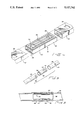
- FIG. 1 is schematic perspective of a hand operated device showing the handle thereof assembled according to the principles of the invention
- FIG. 2 is schematic perspective view of the connector assembly removed from both handle members
- FIG. 3 is schematic cross-sectional view of the connector assembly shown in FIG. 2;
- FIG. 4 is a detailed schematic exploded view of the removable connector assembly and handle members shown in FIG. 1;
- FIG. 5 is a schematic exploded perspective of a further embodiment of the invention.
- FIG. 6 is schematic cross-section of the assembled connector shown in FIG. 6.
- a wheeled device 10 such as a lawnmower, drop spreader or some such other harvesting implement or the like, which is manually operated by means of an elongated handle 12 having a suitable gripping means 14.
- the handle is seen to comprise two separate members 16, 16' which together form the articulated handle 12 when joined by the connector members 18, as shown. While the description below applies to the connector 18 that joins the handle sections 16 and 16', it will be understood that the same operation applies to that connector 18 that joins the lowere end of the central handle section 16' and the lowermost section which is fixed to the wheeled appliance, as shown in FIG. 1.
- the connector assembly housing 18 is shown in detail in FIG. 2, wherein it will be seen that the assembly comprises two halves 20 and 22 divided by a flange member 24, against which abut the respective ends of the handle members 16, 16' when positioned in place on the connector assembly housing.
- the entire assembly is shown to surround a one-piece tubular metal reinforcing member 26, which is made of the same material as the handle members 16, 16'.
- a releasable tab 28 is formed or molded from the connector as a cantilevered member which, owing to the type of plastic used, preferrably a plastic such as ACETAL having an agressive memory, allows the tabs to be pressed downwardly and to be released upwardly to function as a locking means, to be more fully discussed below.
- rib portions 30 and 32 extending longitudinally of the respective half sections 20 and 22. These ribs provide an overall reduced surface area of engagement between the housing 18 and the respective interior surfaces of the handle members 16, 16' and thereby function to facilitate sliding engagement between the handle sections and the connector.
- the tabs 28 are designed to be pressed downwardly into the spaces provided by depressions or pockets 34 in the tubular reinforcing member 26. Also, it will be seen that the rib portions 30 are less high than the rib portions 32. As a result of this discrepancy the half section 22 is slightly larger in overall thickness than section 20, and it is necessary, therefore, to press-fit the central handle member 16' onto the section 22, this being done at the factory and for the purpose of providing a virtually one-time fit in which that part of the connector is not intended to be removed from its respective handle member.
- the other half 20 of the connector owing to its slightly smaller thickness of the ribs 30, is intended to provide a slip-fit for easy assembly which can be released by exerting a nominal amount of force on the other handle member 16, once the tab member 28 is depressed out of its lock-engaging function with the aperture 35 in the handle section 16.
- the tabs 28 are designed to cooperate with the apertures 35 in the respective handle members 16, 16' and thereby provide a locking function for the assembled connector.
- the tabs 28 When the tabs 28 are in place in their respective apertures 35 in the handle members 16, 16' the ends of these members will abut against the flange portion 24, thus forming a smooth uninterrupted outline.
- the reinforcing member 26 is seen to extend the entire length of the connector to thereby provide extra strength to the joint by effectively increasing the thickness of the end portions of the handle sections 16, 16'.
- FIG. 5 A further embodiment of the invention is shown in FIG. 5 in which a tubular connector 36 is shown and is of generally circular cross-section.
- the connector 36 is formed of the same plastic material as connector 18, but unlike connector 18 the connector 36 has a flange 38 formed at one end thereof rather than at the central portion.
- Also provided on the connector 36 is a different arrangement of locking tab members; thus, a pair of opposed locking tab members 40 are provided, and each of these tab members has formed at the free ends thereof a button member 42, as best shown in FIG. 6. It will be seen from FIG. 6 that the handle members 44 and the connector 36 can each be slip-fitted into the other to form a reinforced connection.
- the connector 36 is slip-fitted into one end of one of the handle members so that the end thereof abuts against the flange 38, as shown.
- the button portions 42 of the tab members 40 are then aligned with the apertures 48 in the end of the handle member 44, so that by virtue of the biasing action of the tab members 40 the button portions 42 snap into place.
- One end of the other handle member 46 is shown to be of an enlarged cross-section so that it can be slip-fitted over that end of the other handle member which contains the connector 36, the flange 38 of the connector 36 forming a smooth contiguous surface with the outside surface of handle member 44 to thus enable a slip-fit between the two handle members 44 and 46.
- the releasable button portions 42 of the tab members 40 are aligned with the apertures 48 in the enlarged end-section of the other handle member 46 so that locking engagement between the two handle members can take place.
- Two important fuctions are accomplished by the tabs 42, one, the respective handle members 44 are locked into place, each with respect to the other, and, two, the one member is prevented from rotating with repect to the other.
- the method of assembly of the garden implement according to the invention described with respect to FIGS. 1-4 is as follows. Assuming that the handle 12 of the garden implement 10 is composed of three sections, then a connector 18 will be provided at each end of the central handle section 16', this provision having been made at the factory as a force-fit or press-fit operation. Because of this first step having been conducted at the factory, the user need only slip fit the respective free ends of the connectors 18 at each end of the section 16' into the respective ends of the remaining handle sections provided, that is, the upper section 16, as above described, and, similarly, a lower section fixed to the base of the appliance, as shown in FIG. 1, to thereby assemble a three-piece articulated handle. In the case of a two-piece handle, however, only one connector need be provided on one end of one of the sections in the manner above-described.
- the connector 36 is inserted into one end of the handle member 44 so that the end thereof abuts against the flange 38.
- the connector 36 is then rotated until the locking tabs 42 are aligned with the apertures 48 so that the tabs 42 are locked into place.
- the assembled connector and handle member are then inserted as a unit into the enlarged section of the other handle member 46.
- the apertures 48 on the handle member 46 are aligned with the locking tabs 42 so that the latter lock into place in the respectively aligned apertures.
Abstract
Description
Claims (3)
Priority Applications (1)
| Application Number | Priority Date | Filing Date | Title |
|---|---|---|---|
| US07/318,555 US5127762A (en) | 1989-03-03 | 1989-03-03 | Connector assembly |
Applications Claiming Priority (1)
| Application Number | Priority Date | Filing Date | Title |
|---|---|---|---|
| US07/318,555 US5127762A (en) | 1989-03-03 | 1989-03-03 | Connector assembly |
Publications (1)
| Publication Number | Publication Date |
|---|---|
| US5127762A true US5127762A (en) | 1992-07-07 |
Family
ID=23238671
Family Applications (1)
| Application Number | Title | Priority Date | Filing Date |
|---|---|---|---|
| US07/318,555 Expired - Lifetime US5127762A (en) | 1989-03-03 | 1989-03-03 | Connector assembly |
Country Status (1)
| Country | Link |
|---|---|
| US (1) | US5127762A (en) |
Cited By (76)
| Publication number | Priority date | Publication date | Assignee | Title |
|---|---|---|---|---|
| US5470165A (en) * | 1992-08-12 | 1995-11-28 | Skf Gmbh | Retaining bushing for joining bearing rings |
| US5531464A (en) * | 1994-12-09 | 1996-07-02 | Maurer; Raymond N. | Cart with snap-locking members |
| US5560731A (en) * | 1993-05-10 | 1996-10-01 | Helmut Lingemann | Plug connector for hollow sections |
| US5628580A (en) * | 1995-04-19 | 1997-05-13 | B-Line Systems, Inc. | Splice system |
| US5641237A (en) * | 1995-11-07 | 1997-06-24 | True Temper Hardware Company | Garden tool sleeve |
| US5797501A (en) * | 1996-12-31 | 1998-08-25 | Gunten Lee L Von | Gravity shelf structure support |
| DE29722771U1 (en) * | 1997-12-23 | 1999-04-29 | Kronenberg Max | Connectors for hollow profiles |
| US6443261B1 (en) * | 1999-08-13 | 2002-09-03 | Cosco Management, Inc. | Step stool |
| US20020179130A1 (en) * | 2001-05-30 | 2002-12-05 | Ko Chin Sung | Positioning structure for opening of an umbrella |
| US6533372B1 (en) | 1999-07-16 | 2003-03-18 | Nolu Plastics, Inc. | Beverage cart |
| US20030057022A1 (en) * | 2001-09-23 | 2003-03-27 | Luhao Leng | Hinge structure applied to folding ladder, stool and chair |
| US20030066996A1 (en) * | 2001-09-14 | 2003-04-10 | Crane Plastics Company Llc | Fence assembly with connectors |
| US6568873B1 (en) * | 1999-07-20 | 2003-05-27 | Wallace H. Peterson | In-line connector for window spacer frame tubing |
| US6676326B2 (en) * | 2001-06-25 | 2004-01-13 | Wen-Chang Wu | Square lamp post insertional conjoinment structure |
| US6726255B1 (en) * | 2002-03-25 | 2004-04-27 | James C. Ward | Tube-in-tube joint |
| US20040262479A1 (en) * | 2003-06-30 | 2004-12-30 | Lowrance Electronics, Inc. | Mounting assembly |
| US20050011420A1 (en) * | 2002-12-18 | 2005-01-20 | Frazer Costa | Adjustable closet organizer system |
| US6854919B2 (en) * | 2002-06-20 | 2005-02-15 | S.C. Johnson & Son, Inc. | Push-lock handle assembly |
| US20050109901A1 (en) * | 2002-12-18 | 2005-05-26 | Rubbermaid, Inc. | Shelf mounting bracket for adjustable organizer system |
| US20050109720A1 (en) * | 2002-12-18 | 2005-05-26 | Rubbermaid, Inc. | Method of merchandising an adjustable organizer system |
| US20050145147A1 (en) * | 2002-12-18 | 2005-07-07 | Rubbermaid, Inc. | Top rail assembly for adjustable organizer system |
| US20050145588A1 (en) * | 2002-12-18 | 2005-07-07 | Rubbermaid, Inc. | Mounting upright and clip for adjustable organizer system |
| US20050150850A1 (en) * | 2002-12-18 | 2005-07-14 | Rubbermaid, Inc. | Shoe shelf for adjustable organizer system |
| US20050150436A1 (en) * | 2002-12-18 | 2005-07-14 | Rubbermaid, Inc. | Adjustable length wire shelves for adjustable organizer system |
| EP1557573A1 (en) * | 2004-01-23 | 2005-07-27 | Lisi Automotive Rapid | Device for spaced apart fasteneing of two parts |
| US20050214100A1 (en) * | 2004-03-24 | 2005-09-29 | Kronenberg Ralf M | Multipart plug-type connector |
| US20050252425A1 (en) * | 2004-05-11 | 2005-11-17 | Dardashti Shahriar L | Multimedia storage rack |
| US20060115324A1 (en) * | 2003-06-04 | 2006-06-01 | Kokuyo Co., Ltd. | Member-joining device |
| WO2006117419A1 (en) * | 2005-04-28 | 2006-11-09 | Gaviota Simbac, S.L. | Coupling means for accessories used to operate roller blinds |
| US20070011961A1 (en) * | 2005-06-24 | 2007-01-18 | Annes Jason L | Connector for sash window frame members |
| US20070214743A1 (en) * | 2006-03-17 | 2007-09-20 | Alvarez David J | Tile spacer |
| US20070261174A1 (en) * | 2006-04-25 | 2007-11-15 | Barker Richard W | Modular tools |
| US20070295393A1 (en) * | 2004-05-18 | 2007-12-27 | Akeena Solar, Inc. | Mounting system for a solar panel |
| US20080236967A1 (en) * | 2005-12-17 | 2008-10-02 | Zf Friedrichshafen Ag | Locking Apparatus |
| US20080251674A1 (en) * | 2007-04-13 | 2008-10-16 | Qisda Corporation | Holding apparatus |
| US20080290772A1 (en) * | 2004-10-21 | 2008-11-27 | Changzhou Lingtong Exhibition Products Co., Ltd. | Split Mounting Type Square Column Assembly |
| US20090078299A1 (en) * | 2007-09-21 | 2009-03-26 | Akeena Solar, Inc. | Mounting system for solar panels |
| US20090188206A1 (en) * | 2008-01-24 | 2009-07-30 | Israel Stol | System and method for joining dissimilar materials |
| US20100202824A1 (en) * | 2007-10-03 | 2010-08-12 | Saint-Gobain Glass France | Connector for connecting two hollow section-piece ends |
| US20110000526A1 (en) * | 2007-04-06 | 2011-01-06 | West John R | Pivot-fit frame, system and method for photovoltaic modules |
| US20110070020A1 (en) * | 2009-09-22 | 2011-03-24 | Tabler Charles P | Heavy-Duty Drive Tube Coupling |
| US20110203198A1 (en) * | 2008-10-02 | 2011-08-25 | Max Kronenberg | Insertion connector |
| US20110220180A1 (en) * | 2007-09-21 | 2011-09-15 | Andalay Solar, Inc. | Electrical connectors for solar modules |
| US20110303255A1 (en) * | 2010-06-14 | 2011-12-15 | Easton Technical Products, Inc. | Tent pole connection system and methods |
| US8104145B1 (en) * | 2010-01-02 | 2012-01-31 | Zoya, Inc. | Leash handle with storage drawer and swivel connection |
| US8191192B1 (en) | 2006-04-25 | 2012-06-05 | Barker Richard W | Modular tools |
| US20120243933A1 (en) * | 2009-12-14 | 2012-09-27 | SaarGummi technologies S.à.r.l. | Butt joint between ends of sealing strips or of a sealing strip |
| US20120297684A1 (en) * | 2011-05-24 | 2012-11-29 | David Patrick Bresson | Barrier operator mechanical transmission assembly |
| US8505248B1 (en) | 2007-09-21 | 2013-08-13 | Andalay Solar, Inc. | Minimal ballasted surface mounting system and method |
| US20140099156A1 (en) * | 2012-10-09 | 2014-04-10 | Webasto-Edscha Cabrio GmbH | Bearing Arrangement Having A Bearing Socket |
| US8695290B1 (en) * | 2009-12-07 | 2014-04-15 | Ironridge, Inc. | Systems and methods for splicing solar panel racks |
| US20140137490A1 (en) * | 2010-12-29 | 2014-05-22 | Guardian Industries Corp. | Grid keeper for insulating glass unit, and/or insulating glass unit incorporating the same |
| US8800754B2 (en) | 2009-09-22 | 2014-08-12 | OCS Intellitrak, Inc. | Conveyor system with interchangeable drive tube couplings |
| US20140224290A1 (en) * | 2011-05-19 | 2014-08-14 | Newtec Japan Co., Ltd. | Assembly Tent |
| US8938932B1 (en) * | 2013-12-13 | 2015-01-27 | Quality Product Llc | Rail-less roof mounting system |
| US9154074B2 (en) | 2009-10-06 | 2015-10-06 | Solarcity Corporation | Apparatus for forming and mounting a photovoltaic array |
| US9243817B2 (en) | 2009-07-02 | 2016-01-26 | Solarcity Corporation | Apparatus for forming and mounting a photovoltaic array |
| USD749502S1 (en) | 2010-12-09 | 2016-02-16 | Solarcity Corporation | Combined panel skirt and photovoltaic panels |
| US9320926B2 (en) | 2012-06-28 | 2016-04-26 | Solarcity Corporation | Solar panel fire skirt |
| USD759464S1 (en) | 2010-07-02 | 2016-06-21 | Solarcity Corporation | Leveling foot |
| USD765591S1 (en) | 2011-12-09 | 2016-09-06 | Solarcity Corporation | Panel skirt and photovoltaic panel |
| USD772432S1 (en) | 2010-07-02 | 2016-11-22 | Solarcity Corporation | Panel frame |
| US9518596B2 (en) | 2009-07-02 | 2016-12-13 | Solarcity Corporation | Pivot-fit frame, system and method for photovoltaic modules |
| US9816731B2 (en) | 2010-07-02 | 2017-11-14 | Solarcity Corporation | Pivot-fit connection apparatus and system for photovoltaic arrays |
| US20180056153A1 (en) * | 2016-08-31 | 2018-03-01 | Twin Lacrosse, Inc. | Adjustable Locking Shaft for Sporting Goods |
| US10000964B2 (en) * | 2011-01-21 | 2018-06-19 | Technoform Glass Insulation Holding Gmbh | Connectors for spacers of insulating glass units and spacer comprising a connector for an insulating glass unit |
| EP3470298A1 (en) * | 2017-09-22 | 2019-04-17 | Uwe, Dominik | Stack securing for transport trucks |
| US10302115B2 (en) | 2016-10-18 | 2019-05-28 | Whirlpool Corporation | Spring clip upright connection for rack shelving |
| US20190307646A1 (en) * | 2017-05-01 | 2019-10-10 | Cr Packaging Llc | Child resistant and airtight container |
| USRE47733E1 (en) | 2004-02-05 | 2019-11-19 | Tesla, Inc. | Method and apparatus for mounting photovoltaic modules |
| WO2021148157A1 (en) * | 2020-01-22 | 2021-07-29 | Wanzl GmbH & Co. KGaA | Clamping element and trolley |
| US20220128074A1 (en) * | 2020-10-27 | 2022-04-28 | Robert Varney | Universal coupling for hollow carbon fiber composite structures |
| US20220234159A1 (en) * | 2021-01-27 | 2022-07-28 | Black & Decker Inc. | Pole sander |
| US20230095115A1 (en) * | 2021-09-30 | 2023-03-30 | William Kurt Feick | Wheelbarrow and kit for assembling same |
| US11931851B2 (en) | 2019-10-23 | 2024-03-19 | Black & Decker Inc. | Pole sander |
| FR3139846A1 (en) * | 2022-09-21 | 2024-03-22 | Ocai Distribution | Mason's rule |
Citations (18)
| Publication number | Priority date | Publication date | Assignee | Title |
|---|---|---|---|---|
| US2473388A (en) * | 1945-03-08 | 1949-06-14 | Safway Steel Products Inc | Tubing coupler |
| US2588901A (en) * | 1949-05-19 | 1952-03-11 | Salem Tool Co | Shank and socket connection for augers |
| US2982586A (en) * | 1959-08-07 | 1961-05-02 | Francis J Gliebe | Fishing net construction |
| US3269754A (en) * | 1964-03-02 | 1966-08-30 | Mc Graw Edison Co | Internal plastic coupling |
| US3294429A (en) * | 1964-03-30 | 1966-12-27 | Nickolas J Halip | Display board assembly and parts thereof |
| US3446523A (en) * | 1966-10-19 | 1969-05-27 | Coleman Co | Self-locking adjustable tent pole |
| US3521913A (en) * | 1968-08-26 | 1970-07-28 | Donald Verhein | Tube coupling |
| US3533513A (en) * | 1967-04-25 | 1970-10-13 | Capitol Hardware Mfg Co Inc | Circular garment rack |
| DE2024508A1 (en) * | 1970-05-20 | 1971-12-16 | Hanning Kunststoffe R Hanning | Pipe connection system |
| US3811455A (en) * | 1971-10-21 | 1974-05-21 | Telesco Brophey Ltd | Telescopic umbrella stick |
| US3883257A (en) * | 1973-11-05 | 1975-05-13 | Lane Company Inc | Molded joint component for tubular frame furniture |
| US3980409A (en) * | 1973-11-14 | 1976-09-14 | Square D Company | Extensible tool for handling energized electric equipment |
| US4068346A (en) * | 1975-12-12 | 1978-01-17 | Josef Binder | Handle for a hand implement such as a rake, a broom, or the like |
| US4135835A (en) * | 1976-04-28 | 1979-01-23 | Hoover Universal, Inc. | Latch unit for adjustable bed frame rails |
| US4323319A (en) * | 1977-01-17 | 1982-04-06 | Adams Bevoley C | Structural connecting member |
| US4640572A (en) * | 1984-08-10 | 1987-02-03 | Conlon Thomas R | Connector for structural systems |
| US4802294A (en) * | 1986-05-03 | 1989-02-07 | Baus Heinz Georg | Frame, more particularly for a picture |
| US4903924A (en) * | 1988-01-28 | 1990-02-27 | Embru-Werke, Mantel & Cie. | Coupling for the detachable connecting of two coaxial pipes and carrying column for a room divider containing the coupling |
-
1989
- 1989-03-03 US US07/318,555 patent/US5127762A/en not_active Expired - Lifetime
Patent Citations (18)
| Publication number | Priority date | Publication date | Assignee | Title |
|---|---|---|---|---|
| US2473388A (en) * | 1945-03-08 | 1949-06-14 | Safway Steel Products Inc | Tubing coupler |
| US2588901A (en) * | 1949-05-19 | 1952-03-11 | Salem Tool Co | Shank and socket connection for augers |
| US2982586A (en) * | 1959-08-07 | 1961-05-02 | Francis J Gliebe | Fishing net construction |
| US3269754A (en) * | 1964-03-02 | 1966-08-30 | Mc Graw Edison Co | Internal plastic coupling |
| US3294429A (en) * | 1964-03-30 | 1966-12-27 | Nickolas J Halip | Display board assembly and parts thereof |
| US3446523A (en) * | 1966-10-19 | 1969-05-27 | Coleman Co | Self-locking adjustable tent pole |
| US3533513A (en) * | 1967-04-25 | 1970-10-13 | Capitol Hardware Mfg Co Inc | Circular garment rack |
| US3521913A (en) * | 1968-08-26 | 1970-07-28 | Donald Verhein | Tube coupling |
| DE2024508A1 (en) * | 1970-05-20 | 1971-12-16 | Hanning Kunststoffe R Hanning | Pipe connection system |
| US3811455A (en) * | 1971-10-21 | 1974-05-21 | Telesco Brophey Ltd | Telescopic umbrella stick |
| US3883257A (en) * | 1973-11-05 | 1975-05-13 | Lane Company Inc | Molded joint component for tubular frame furniture |
| US3980409A (en) * | 1973-11-14 | 1976-09-14 | Square D Company | Extensible tool for handling energized electric equipment |
| US4068346A (en) * | 1975-12-12 | 1978-01-17 | Josef Binder | Handle for a hand implement such as a rake, a broom, or the like |
| US4135835A (en) * | 1976-04-28 | 1979-01-23 | Hoover Universal, Inc. | Latch unit for adjustable bed frame rails |
| US4323319A (en) * | 1977-01-17 | 1982-04-06 | Adams Bevoley C | Structural connecting member |
| US4640572A (en) * | 1984-08-10 | 1987-02-03 | Conlon Thomas R | Connector for structural systems |
| US4802294A (en) * | 1986-05-03 | 1989-02-07 | Baus Heinz Georg | Frame, more particularly for a picture |
| US4903924A (en) * | 1988-01-28 | 1990-02-27 | Embru-Werke, Mantel & Cie. | Coupling for the detachable connecting of two coaxial pipes and carrying column for a room divider containing the coupling |
Cited By (129)
| Publication number | Priority date | Publication date | Assignee | Title |
|---|---|---|---|---|
| US5470165A (en) * | 1992-08-12 | 1995-11-28 | Skf Gmbh | Retaining bushing for joining bearing rings |
| US5560731A (en) * | 1993-05-10 | 1996-10-01 | Helmut Lingemann | Plug connector for hollow sections |
| US5531464A (en) * | 1994-12-09 | 1996-07-02 | Maurer; Raymond N. | Cart with snap-locking members |
| US5628580A (en) * | 1995-04-19 | 1997-05-13 | B-Line Systems, Inc. | Splice system |
| US5720567A (en) * | 1995-04-19 | 1998-02-24 | Sigma-Aldrich Company | Cable tray system |
| US5641237A (en) * | 1995-11-07 | 1997-06-24 | True Temper Hardware Company | Garden tool sleeve |
| US5797501A (en) * | 1996-12-31 | 1998-08-25 | Gunten Lee L Von | Gravity shelf structure support |
| DE29722771U1 (en) * | 1997-12-23 | 1999-04-29 | Kronenberg Max | Connectors for hollow profiles |
| US6533372B1 (en) | 1999-07-16 | 2003-03-18 | Nolu Plastics, Inc. | Beverage cart |
| US6568873B1 (en) * | 1999-07-20 | 2003-05-27 | Wallace H. Peterson | In-line connector for window spacer frame tubing |
| US6443261B1 (en) * | 1999-08-13 | 2002-09-03 | Cosco Management, Inc. | Step stool |
| US20020179130A1 (en) * | 2001-05-30 | 2002-12-05 | Ko Chin Sung | Positioning structure for opening of an umbrella |
| US6676326B2 (en) * | 2001-06-25 | 2004-01-13 | Wen-Chang Wu | Square lamp post insertional conjoinment structure |
| US20040188665A1 (en) * | 2001-09-14 | 2004-09-30 | Crane Plastics Company Llc | Fence assembly with connectors |
| US6935623B2 (en) | 2001-09-14 | 2005-08-30 | Crane Plastics Company Llc | Fence assembly with connectors |
| US20030066996A1 (en) * | 2001-09-14 | 2003-04-10 | Crane Plastics Company Llc | Fence assembly with connectors |
| US20030057022A1 (en) * | 2001-09-23 | 2003-03-27 | Luhao Leng | Hinge structure applied to folding ladder, stool and chair |
| US6726255B1 (en) * | 2002-03-25 | 2004-04-27 | James C. Ward | Tube-in-tube joint |
| US6854919B2 (en) * | 2002-06-20 | 2005-02-15 | S.C. Johnson & Son, Inc. | Push-lock handle assembly |
| US20050150850A1 (en) * | 2002-12-18 | 2005-07-14 | Rubbermaid, Inc. | Shoe shelf for adjustable organizer system |
| US7387212B2 (en) | 2002-12-18 | 2008-06-17 | Rubbermaid Incorporated | Top rail assembly for adjustable organizer system |
| US20050109720A1 (en) * | 2002-12-18 | 2005-05-26 | Rubbermaid, Inc. | Method of merchandising an adjustable organizer system |
| US20050145147A1 (en) * | 2002-12-18 | 2005-07-07 | Rubbermaid, Inc. | Top rail assembly for adjustable organizer system |
| US20050145588A1 (en) * | 2002-12-18 | 2005-07-07 | Rubbermaid, Inc. | Mounting upright and clip for adjustable organizer system |
| US20050011420A1 (en) * | 2002-12-18 | 2005-01-20 | Frazer Costa | Adjustable closet organizer system |
| US20050150436A1 (en) * | 2002-12-18 | 2005-07-14 | Rubbermaid, Inc. | Adjustable length wire shelves for adjustable organizer system |
| US7240803B2 (en) * | 2002-12-18 | 2007-07-10 | Rubbermaid, Inc. | Shelf mounting bracket for adjustable organizer system |
| US7188740B2 (en) | 2002-12-18 | 2007-03-13 | Rubbermaid, Inc. | Adjustable length wire shelves for adjustable organizer system |
| US7392911B2 (en) | 2002-12-18 | 2008-07-01 | Rubbermaid, Inc. | Shelf mounting bracket for adjustable organizer system |
| US20050109901A1 (en) * | 2002-12-18 | 2005-05-26 | Rubbermaid, Inc. | Shelf mounting bracket for adjustable organizer system |
| US7255237B2 (en) * | 2002-12-18 | 2007-08-14 | Rubbermaid Incorporated | Mounting upright and clip for adjustable organizer system |
| US7314144B2 (en) | 2002-12-18 | 2008-01-01 | Rubbermaid, Inc. | Shoe shelf for adjustable organizer system |
| US7296697B2 (en) * | 2002-12-18 | 2007-11-20 | Rubbermaid Incorporated | Adjustable closet organizer system |
| US20060115324A1 (en) * | 2003-06-04 | 2006-06-01 | Kokuyo Co., Ltd. | Member-joining device |
| US7524130B2 (en) * | 2003-06-04 | 2009-04-28 | Kokuyo Co., Ltd. | Member-joining device |
| US7520481B2 (en) | 2003-06-30 | 2009-04-21 | Navico, Inc. | Mounting assembly |
| US7063297B2 (en) | 2003-06-30 | 2006-06-20 | Lowrance Electronics, Inc. | Mounting assembly |
| US20040262479A1 (en) * | 2003-06-30 | 2004-12-30 | Lowrance Electronics, Inc. | Mounting assembly |
| EP1557573A1 (en) * | 2004-01-23 | 2005-07-27 | Lisi Automotive Rapid | Device for spaced apart fasteneing of two parts |
| USRE47733E1 (en) | 2004-02-05 | 2019-11-19 | Tesla, Inc. | Method and apparatus for mounting photovoltaic modules |
| US7070356B2 (en) * | 2004-03-24 | 2006-07-04 | Ralf Max Kronenberg | Multipart plug-type connector |
| US20050214100A1 (en) * | 2004-03-24 | 2005-09-29 | Kronenberg Ralf M | Multipart plug-type connector |
| US20050252425A1 (en) * | 2004-05-11 | 2005-11-17 | Dardashti Shahriar L | Multimedia storage rack |
| US7866098B2 (en) * | 2004-05-18 | 2011-01-11 | Andalay Solar, Inc. | Mounting system for a solar panel |
| US20070295393A1 (en) * | 2004-05-18 | 2007-12-27 | Akeena Solar, Inc. | Mounting system for a solar panel |
| US20070295392A1 (en) * | 2004-05-18 | 2007-12-27 | Akeena Solar, Inc. | Mounting system for a solar panel |
| US7987641B2 (en) | 2004-05-18 | 2011-08-02 | Andalay Solar, Inc. | Mounting system for a solar panel |
| US20080290772A1 (en) * | 2004-10-21 | 2008-11-27 | Changzhou Lingtong Exhibition Products Co., Ltd. | Split Mounting Type Square Column Assembly |
| WO2006117419A1 (en) * | 2005-04-28 | 2006-11-09 | Gaviota Simbac, S.L. | Coupling means for accessories used to operate roller blinds |
| US7628562B2 (en) * | 2005-06-24 | 2009-12-08 | Newell Operating Company | Connector for sash window frame members |
| US20070011961A1 (en) * | 2005-06-24 | 2007-01-18 | Annes Jason L | Connector for sash window frame members |
| US9062766B2 (en) * | 2005-12-17 | 2015-06-23 | Zf Friedrichshafen Ag | Locking apparatus |
| US20080236967A1 (en) * | 2005-12-17 | 2008-10-02 | Zf Friedrichshafen Ag | Locking Apparatus |
| US20070214743A1 (en) * | 2006-03-17 | 2007-09-20 | Alvarez David J | Tile spacer |
| US7818923B2 (en) * | 2006-03-17 | 2010-10-26 | Alvarez David J | Tile spacer |
| US8191192B1 (en) | 2006-04-25 | 2012-06-05 | Barker Richard W | Modular tools |
| US20070261174A1 (en) * | 2006-04-25 | 2007-11-15 | Barker Richard W | Modular tools |
| US20110000526A1 (en) * | 2007-04-06 | 2011-01-06 | West John R | Pivot-fit frame, system and method for photovoltaic modules |
| US8919052B2 (en) | 2007-04-06 | 2014-12-30 | Zep Solar, Llc | Pivot-fit frame, system and method for photovoltaic modules |
| US20080251674A1 (en) * | 2007-04-13 | 2008-10-16 | Qisda Corporation | Holding apparatus |
| US8938919B2 (en) | 2007-09-21 | 2015-01-27 | Andalay Solar, Inc. | Electrical connectors for solar modules |
| US8505248B1 (en) | 2007-09-21 | 2013-08-13 | Andalay Solar, Inc. | Minimal ballasted surface mounting system and method |
| US20090078299A1 (en) * | 2007-09-21 | 2009-03-26 | Akeena Solar, Inc. | Mounting system for solar panels |
| US20110220180A1 (en) * | 2007-09-21 | 2011-09-15 | Andalay Solar, Inc. | Electrical connectors for solar modules |
| US8813460B2 (en) | 2007-09-21 | 2014-08-26 | Andalay Solar, Inc. | Mounting system for solar panels |
| US20100202824A1 (en) * | 2007-10-03 | 2010-08-12 | Saint-Gobain Glass France | Connector for connecting two hollow section-piece ends |
| US20090188206A1 (en) * | 2008-01-24 | 2009-07-30 | Israel Stol | System and method for joining dissimilar materials |
| US9496821B2 (en) | 2008-04-08 | 2016-11-15 | Solarcity Corporation | Method and apparatus for forming and mounting a photovoltaic array |
| US20110203198A1 (en) * | 2008-10-02 | 2011-08-25 | Max Kronenberg | Insertion connector |
| US8615961B2 (en) * | 2008-10-02 | 2013-12-31 | Max Kronenberg | Insertion connector |
| US9574588B2 (en) | 2009-07-02 | 2017-02-21 | Solarcity Corporation | Method and apparatus for forming and mounting a photovoltaic array |
| US9518596B2 (en) | 2009-07-02 | 2016-12-13 | Solarcity Corporation | Pivot-fit frame, system and method for photovoltaic modules |
| US20110000520A1 (en) * | 2009-07-02 | 2011-01-06 | West John R | Leveling foot apparatus, system, and method for photovoltaic arrays |
| US9853597B2 (en) | 2009-07-02 | 2017-12-26 | Solarcity Corporation | Pivot-fit connection apparatus, system, and method for photovoltaic modules |
| US9831818B2 (en) | 2009-07-02 | 2017-11-28 | Solarcity Corporation | Pivot-fit frame, system and method for photovoltaic modules |
| US9599280B2 (en) | 2009-07-02 | 2017-03-21 | Solarcity Corporation | Pivot-fit frame, system and method for photovoltaic modules |
| US9447801B2 (en) | 2009-07-02 | 2016-09-20 | Solarcity Corporation | Apparatus for forming and mounting a photovoltaic array |
| US8991114B2 (en) | 2009-07-02 | 2015-03-31 | Zep Solar, Llc | Pivot-fit connection apparatus, system, and method for photovoltaic modules |
| US20110000519A1 (en) * | 2009-07-02 | 2011-01-06 | West John R | Pivot-fit connection apparatus, system, and method for photovoltaic modules |
| US8919053B2 (en) | 2009-07-02 | 2014-12-30 | Zep Solar, Llc | Leveling foot apparatus, system, and method for photovoltaic arrays |
| US20110000544A1 (en) * | 2009-07-02 | 2011-01-06 | West John R | Drop-in connection apparatus, system, and method for photovoltaic arrays |
| US9243817B2 (en) | 2009-07-02 | 2016-01-26 | Solarcity Corporation | Apparatus for forming and mounting a photovoltaic array |
| US20110070020A1 (en) * | 2009-09-22 | 2011-03-24 | Tabler Charles P | Heavy-Duty Drive Tube Coupling |
| US8800754B2 (en) | 2009-09-22 | 2014-08-12 | OCS Intellitrak, Inc. | Conveyor system with interchangeable drive tube couplings |
| US9154074B2 (en) | 2009-10-06 | 2015-10-06 | Solarcity Corporation | Apparatus for forming and mounting a photovoltaic array |
| US9300244B2 (en) | 2009-10-06 | 2016-03-29 | Solarcity Corporation | Apparatus for forming and mounting a photovoltaic array |
| US8695290B1 (en) * | 2009-12-07 | 2014-04-15 | Ironridge, Inc. | Systems and methods for splicing solar panel racks |
| US20120243933A1 (en) * | 2009-12-14 | 2012-09-27 | SaarGummi technologies S.à.r.l. | Butt joint between ends of sealing strips or of a sealing strip |
| US8104145B1 (en) * | 2010-01-02 | 2012-01-31 | Zoya, Inc. | Leash handle with storage drawer and swivel connection |
| US8776813B2 (en) * | 2010-06-14 | 2014-07-15 | Easton Technical Products, Inc. | Tent pole connection system and methods |
| US20110303255A1 (en) * | 2010-06-14 | 2011-12-15 | Easton Technical Products, Inc. | Tent pole connection system and methods |
| USD812457S1 (en) | 2010-07-02 | 2018-03-13 | Solarcity Corporation | Coupling |
| USD759464S1 (en) | 2010-07-02 | 2016-06-21 | Solarcity Corporation | Leveling foot |
| USD817741S1 (en) | 2010-07-02 | 2018-05-15 | Solarcity Corporation | Leveling foot |
| US9816731B2 (en) | 2010-07-02 | 2017-11-14 | Solarcity Corporation | Pivot-fit connection apparatus and system for photovoltaic arrays |
| USD772432S1 (en) | 2010-07-02 | 2016-11-22 | Solarcity Corporation | Panel frame |
| USD749502S1 (en) | 2010-12-09 | 2016-02-16 | Solarcity Corporation | Combined panel skirt and photovoltaic panels |
| US9291369B2 (en) | 2010-12-09 | 2016-03-22 | Solarcity Corporation | Skirt for photovoltaic arrays |
| US20140137490A1 (en) * | 2010-12-29 | 2014-05-22 | Guardian Industries Corp. | Grid keeper for insulating glass unit, and/or insulating glass unit incorporating the same |
| US9074417B2 (en) * | 2010-12-29 | 2015-07-07 | Guardian Industries Corp. | Grid keeper for insulating glass unit, and/or insulating glass unit incorporating the same |
| US10000964B2 (en) * | 2011-01-21 | 2018-06-19 | Technoform Glass Insulation Holding Gmbh | Connectors for spacers of insulating glass units and spacer comprising a connector for an insulating glass unit |
| US20140224290A1 (en) * | 2011-05-19 | 2014-08-14 | Newtec Japan Co., Ltd. | Assembly Tent |
| US9169664B2 (en) * | 2011-05-19 | 2015-10-27 | Newtec Japan Co., Ltd. | Assembly tent |
| US20120297684A1 (en) * | 2011-05-24 | 2012-11-29 | David Patrick Bresson | Barrier operator mechanical transmission assembly |
| US9752369B2 (en) * | 2011-05-24 | 2017-09-05 | Overhead Door Corporation | Barrier operator mechanical transmission assembly |
| US10584527B2 (en) | 2011-05-24 | 2020-03-10 | Overhead Door Corporation | Barrier operator mechanical transmission assembly |
| USD765591S1 (en) | 2011-12-09 | 2016-09-06 | Solarcity Corporation | Panel skirt and photovoltaic panel |
| US9320926B2 (en) | 2012-06-28 | 2016-04-26 | Solarcity Corporation | Solar panel fire skirt |
| US20140099156A1 (en) * | 2012-10-09 | 2014-04-10 | Webasto-Edscha Cabrio GmbH | Bearing Arrangement Having A Bearing Socket |
| US9534627B2 (en) * | 2012-10-09 | 2017-01-03 | Webasto-Edscha Cabrio GmbH | Bearing arrangement having a bearing socket |
| US8938932B1 (en) * | 2013-12-13 | 2015-01-27 | Quality Product Llc | Rail-less roof mounting system |
| US20180056153A1 (en) * | 2016-08-31 | 2018-03-01 | Twin Lacrosse, Inc. | Adjustable Locking Shaft for Sporting Goods |
| US10302115B2 (en) | 2016-10-18 | 2019-05-28 | Whirlpool Corporation | Spring clip upright connection for rack shelving |
| US20190307646A1 (en) * | 2017-05-01 | 2019-10-10 | Cr Packaging Llc | Child resistant and airtight container |
| US11547634B2 (en) | 2017-05-01 | 2023-01-10 | Cr Packaging Llc | Modular system for inventory and transport efficiency of packaging |
| US10799424B2 (en) * | 2017-05-01 | 2020-10-13 | Cr Packaging Llc | Child resistant and airtight container |
| US11896554B2 (en) | 2017-05-01 | 2024-02-13 | Cr Packaging Llc | Child resistant and airtight container |
| EP3470298A1 (en) * | 2017-09-22 | 2019-04-17 | Uwe, Dominik | Stack securing for transport trucks |
| EP3470298B1 (en) | 2017-09-22 | 2023-06-14 | Uwe, Dominik | Stack securing for transport trucks |
| US11931851B2 (en) | 2019-10-23 | 2024-03-19 | Black & Decker Inc. | Pole sander |
| CN114667249A (en) * | 2020-01-22 | 2022-06-24 | 旺众有限及股份两合公司 | Clamping element and transport vehicle |
| WO2021148157A1 (en) * | 2020-01-22 | 2021-07-29 | Wanzl GmbH & Co. KGaA | Clamping element and trolley |
| US20220128074A1 (en) * | 2020-10-27 | 2022-04-28 | Robert Varney | Universal coupling for hollow carbon fiber composite structures |
| US20220234159A1 (en) * | 2021-01-27 | 2022-07-28 | Black & Decker Inc. | Pole sander |
| US11867224B2 (en) * | 2021-01-27 | 2024-01-09 | Black & Decker Inc. | Locking mechanism for two telescoping poles of a power tool |
| US20230095115A1 (en) * | 2021-09-30 | 2023-03-30 | William Kurt Feick | Wheelbarrow and kit for assembling same |
| US11738789B2 (en) * | 2021-09-30 | 2023-08-29 | William Kurt Feick | Wheelbarrow and kit for assembling same |
| US20230347953A1 (en) * | 2021-09-30 | 2023-11-02 | William Kurt Feick | Wheelbarrow and kit for assembling same |
| FR3139846A1 (en) * | 2022-09-21 | 2024-03-22 | Ocai Distribution | Mason's rule |
Similar Documents
| Publication | Publication Date | Title |
|---|---|---|
| US5127762A (en) | Connector assembly | |
| US6925686B2 (en) | Twist-lock handle assembly | |
| US6193265B1 (en) | Wheelbarrow | |
| US7171724B2 (en) | Multifunctional electric cleaning apparatus | |
| US5138911A (en) | Telescopic wrench extensioner | |
| US20030235463A1 (en) | Push-lock handle assembly | |
| US4539751A (en) | Barbeque forks | |
| US4380885A (en) | Hoop toy | |
| US6834670B2 (en) | Hose reel cart with folding crank handle | |
| US6779235B2 (en) | Universal tool handle configured for various extension pole connectors | |
| US5046520A (en) | Portable hose cart | |
| EP1600098A2 (en) | Locking, segmented cleaning implement handle | |
| US4697949A (en) | Plug, socket and plug-and-socket coupling thereof for temporarily attaching an implement to a handle | |
| US5007598A (en) | Hose reel assembly | |
| CA2217141A1 (en) | Portable hose cart assembly | |
| US10603779B2 (en) | Adaptable pole for a pool device | |
| US20070290486A1 (en) | Collapsible barbecue cart | |
| US20040156674A1 (en) | Joint between tubes of a tube combination having annular trenches | |
| US4155143A (en) | Separable handle for cleaner | |
| US3727956A (en) | Demountable handle assembly | |
| US6854812B2 (en) | Wheel axle design of gas grill | |
| US5345960A (en) | Connecting piece for large umbrellas | |
| EP0181694A1 (en) | Vacuum cleaner extension tube system | |
| KR200184362Y1 (en) | A folding type hulahoop | |
| EP0911292A1 (en) | Irrigation hose winding cart |
Legal Events
| Date | Code | Title | Description |
|---|---|---|---|
| AS | Assignment |
Owner name: REPUBLIC TOOL & MANUFACTURING CORP., CALIFORNIA Free format text: ASSIGNMENT OF ASSIGNORS INTEREST.;ASSIGNOR:HAVLOVITZ, PAUL;REEL/FRAME:005129/0160 Effective date: 19890216 |
|
| STCF | Information on status: patent grant |
Free format text: PATENTED CASE |
|
| AS | Assignment |
Owner name: CHEMICAL BANK, NEW YORK Free format text: SECURITY INTEREST;ASSIGNOR:REPUBLIC TOOL & MANUFACTURING CORP.;REEL/FRAME:006336/0904 Effective date: 19921119 |
|
| FEPP | Fee payment procedure |
Free format text: PAT HLDR NO LONGER CLAIMS SMALL ENT STAT AS SMALL BUSINESS (ORIGINAL EVENT CODE: LSM2); ENTITY STATUS OF PATENT OWNER: LARGE ENTITY |
|
| AS | Assignment |
Owner name: REPUBLIC TOOL & MANUFACTURING CORP., OHIO Free format text: RELEASE BY SECURED PARTY;ASSIGNOR:CHEMICAL BANK;REEL/FRAME:007437/0318 Effective date: 19950317 Owner name: REPUBLIC TOOL & MANUFACTURING CORP., OHIO Free format text: RELEASE BY SECURED PARTY;ASSIGNOR:CHEMICAL BANK;REEL/FRAME:007439/0060 Effective date: 19950317 |
|
| FPAY | Fee payment |
Year of fee payment: 4 |
|
| AS | Assignment |
Owner name: OMS INVESTMENTS, INC., DELAWARE Free format text: ASSIGNMENT OF ASSIGNORS INTEREST;ASSIGNOR:REPUBLIC TOOL & MANUFACTURING CORPORATION;REEL/FRAME:010247/0344 Effective date: 19990301 |
|
| AS | Assignment |
Owner name: CHASE MANHATTAN BANK, AS ADMINISTRATIVE AGENT, THE Free format text: SECURITY INTEREST;ASSIGNOR:OMS INVESTMENTS, INC.;REEL/FRAME:010506/0462 Effective date: 19990121 |
|
| REMI | Maintenance fee reminder mailed | ||
| FPAY | Fee payment |
Year of fee payment: 8 |
|
| SULP | Surcharge for late payment | ||
| FPAY | Fee payment |
Year of fee payment: 12 |
|
| AS | Assignment |
Owner name: OMS INVESTMENTS, INC., CALIFORNIA Free format text: TERMINATION AND RELEASE OF SECURITY INTEREST IN PATENT RIGHTS (PREVIOUSLY RECORDED AT REEL 10506 FRAME 0462);ASSIGNOR:JPMORGAN CHASE BANK, N.A., AS ADMINISTRATIVE AGENT (FORMERLY KNOWN AS THE CHASE MANHATTAN BANK);REEL/FRAME:016674/0409 Effective date: 20051019 |
|
| FEPP | Fee payment procedure |
Free format text: PAYOR NUMBER ASSIGNED (ORIGINAL EVENT CODE: ASPN); ENTITY STATUS OF PATENT OWNER: LARGE ENTITY |