US1853672A - Pocket knife - Google Patents
Pocket knife Download PDFInfo
- Publication number
- US1853672A US1853672A US542859A US54285931A US1853672A US 1853672 A US1853672 A US 1853672A US 542859 A US542859 A US 542859A US 54285931 A US54285931 A US 54285931A US 1853672 A US1853672 A US 1853672A
- Authority
- US
- United States
- Prior art keywords
- blade
- casing
- slot
- spring
- collar
- Prior art date
- Legal status (The legal status is an assumption and is not a legal conclusion. Google has not performed a legal analysis and makes no representation as to the accuracy of the status listed.)
- Expired - Lifetime
Links
Images
Classifications
-
- B—PERFORMING OPERATIONS; TRANSPORTING
- B26—HAND CUTTING TOOLS; CUTTING; SEVERING
- B26B—HAND-HELD CUTTING TOOLS NOT OTHERWISE PROVIDED FOR
- B26B1/00—Hand knives with adjustable blade; Pocket knives
- B26B1/08—Hand knives with adjustable blade; Pocket knives with sliding blade
Definitions
- This invention relates to improvements in ocket knives and has special reference to Bnives having slidable b ades in contradistinction to pivoted blades.
- the object of the inventlon 1s to provide a knife of this character, in which the blade can be readily extended to a plurality of positions and be firmly held in each of such p0- sitions; in which the blade when fully prol0 jected shall be rigidly held to withstand the strains of use; to provide a knife of this character in which the blade can easily and readily be replaced when broken.
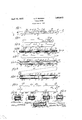
- FIG. 1 is a plan view of one side of a pocket knife embodying the invention in one form, the knife blade being shown extended in dotted lines;
- Fig. 2 is a view sim'lar to Fig. 1, but showing the opposite side;
- Fig. 3 1s a plan view of the kmfe blade
- Fig. 4 is a longitudinal, central section on 30 the line 4-4 of Fig. 1;
- Figs. 5 and 6 are plan sections on the lines 5-5 and 6-6, respectively, of Fig. 3;
- Fig. 7 is a plan view of a fiat spring which is used in the structure
- Fig. 8 is a fragmentary, perspective view of the outside tubular coverbefore it is put on;
- Fig. 9 is a plan view of the sheet metal frame before it is formed up;
- Figs. 10, 11 and 12 are transverse sections on the lines 10-10; 11-11 and12-12, respectively, of Fig. 5;
- Fig. 13 is a transverse section on the line 13--13 of Fig. 4;
- Fig. 14 is a fragmentary, longitudinal, vertical section on the line 14--14 of Figs. 1v and 13.
- 1 represents a double ended knife blade which is used in the form of the invention illustrated inthe drawings.
- the blade preferably, is made with one form of point 2 at one end and another form 3' at the other'end. JThese different forms of points are used for different purposes.
- the cutting edges 4 of the two ends are preferably oppositely ldisposed for a purpose to be explained later.
- the middle portion 5 of the blade has parallel edges 6 .which ex' tend slightlybeyond vthe cutting edges 4 of thJ1 ends and flush with the backs 7 of the en s.
- the blade 1 has a threaded hole 8 at its center for the purpose of rigidly mounting a button 9 for use inprojecting and withdrawing the blade.
- the blade is arranged within a sheet metal frame or housing 10, which is made in the form of a attened tube of an interior width d to fit' the central parallel part 5 of the blade,
- the button 9 has a threaded point adapted to be screwed tightly into the threaded hole 8 in the blade, and a thin collar 12 to limit the engagement of the button with vthe blade and ⁇ to provide a stop for rigidly retaining the blade in its adjusted positions.
- the button 9 has a shank 13 smaller in diameter than the collar and which projects through an elongated slot 14 in the casing and through which the button is moved back and forth in projecting and withdrawing the blade.
- the buLtton 9 has an enlarged head 15 for engagement by allie thumb in projecting and withdrawing the ade.
- the collar 12 on the button 9 is lar er in diameter than the width of the slot 14 1n the casing 10 and the slot is enlarged at various points to receive the collar for retaining the blade in its adjusted positions.
- One enlar ement 16 is arranged at the center to receive t e collar 12 when the blade -is in mid-position with both ends within the casing, in other words, when the knife is closed.
- Other enlargements 17 near the ends of thecasing receive the collar when the ends are fully extended, and intermediate enlargements 18 receive the collar 12 when the blade is posi- 100 tioned to partially extend the ends.
- Thls spring is arranged beneath the blade and is nearly as long as the casing and is bowed up to give it sufficient tension to press the blade firmly against the upper wall of the casing, as best shown in Fig. 3.
- the ends of the spring are ointed, as shown at'20, and are formed to project into holes 21 in the lower wall of the casing to retain the spring against endwise displacement when the blade is moved endwise.
- the end portions of the bottom wall of the casing are deiiected or bent toward the top wall of the casing, as shown at 22, to decrease the height of the end openings of the casing to substantially the thickness of the blade. This formation assists in holding the blade rigidly when an end is projected.
- the blade is first depressed by pushing in on the button 9 against the pressure of the spring 19 to free the collar 12 from the casing, thenthe blade is free to be pushed endwise by the button 9.
- the button 9 is free of inward pressure, it is forced against the top -wall of -the casing and, if the blade is moved endwise at this time, the collar 12 will be forced into any of Athe enlargements of the slot 14 when in registry'therewith. This engagement then locks the blade against endwise movement.
- any pressure on the cutting edge of a projected end tends to force the back edge of the opposite end against the casing.
- the holding of the middle part 5 of the blade is thus reinforced by the back of the enclosed end of the' blade and neither sharp edge is forced against the casing but is always clear of same.
- strip of the sheet metal is first formedof a contour so that when made into a flattened, v
- the lateral edges 23 will be brought together on the longitudinal center line of the top wall of the casing, as shown at 24, Figs. 5 and 13.
- the lateral edge portions are c-ut away, as shown at 25 and 26, Fig. 9, while the metal is in flat form to provide the slot 14 and the enlargements 16, 17 and 18 of the slot when the casing is formed.
- the holes 21 for the ends of the spring 19 are punched while the casing member 'is flat, as also a hole 27 for use in se- 5 curing a pocket clip 28 by means of a rivet 29.
- each longitudinal half of the casing is U-shaped and quite rigid as related to any pressure exerted by the spring 19.
- the steel outof which the case 10 is made must be soft enough to be readily bent into shape in suitable dies, it might possibly tend to give or be fo'rced out of shape in use and to prevent any possibility of such an effect, the steel of which it is made is such that it can be tempered or hardened. To avoid any wear on the collar 12 of the button 9 as it is slid along from one position to another, it is also hardened.
- a pocket knife a double ended blade, a casing in which the blade is longitudinally movable to project and withdraw either end, a rigid projection on the blade, the casing provided with a longitudinal slot through which the projection extends, a collar on the projection adjacent to the blade, the slot being enlarged at a plurality of points for receiving the collar, and a spring in the casing adapted to yieldingly hold the blade pressed in a direction to cause the collar to enter one of the enlargements of the slot.
- a pocket knife of the kind described ay tubular metal casing, a knife blade longitudinally movable in the casing, the casing having a longitudinal slot in one side, a projection4 on the blade extending through the slot for use in moving the blade, an enlargement on the projection adjacent to the blade, the slot being enlarged at specified points to receive the said enlargement to ho d the blade against longitudinal movement, and a cover on the ⁇ casing having a longitudinal slot registering with the slot in the casing and formed to cover some of said enlargements of the slot in the casing.
- a pocket knife of the kind described a tubular casing, a knife blade longitudinally movable in the casing, the casing having a lon 'tudinal slot in one side, a projection on the lade extendin through the slot for use in moving the bla e, an enlargement on the projection within the casing, the slot being enlarged at specified points to receive the said enlargement to hold the blade against lon ltudinal movement, and a. cover on thecasmg having a longitudinal slot registering with the slot in the casing and formed to cover some of said enlargements of the slot in the casing.
Description
A. F; DoDsoN 1,853,672
POCKET KNIFE April4 l2, 1932.
Filed June 8. 193i 52 1MM Tv/ff@ 6 '5 QE-:ffm
Ak' V j 4 (6` 7 l 13 Patented Apr. 12, 1932 Loma r. Bonson, or omcaeo; :mnmors rocxEr mr.
application mea :une s. 1931. semi m. 542,859.
This invention relates to improvements in ocket knives and has special reference to Bnives having slidable b ades in contradistinction to pivoted blades.
l The object of the inventlon 1s to provide a knife of this character, in which the blade can be readily extended to a plurality of positions and be firmly held in each of such p0- sitions; in which the blade when fully prol0 jected shall be rigidly held to withstand the strains of use; to provide a knife of this character in which the blade can easily and readily be replaced when broken.
Many features of the invention relate to l the knife case and improved ways and means for producing and finishing same.
Further novel features of importance will be made clear fromthe following descrlption taken in conjunction with the appende S0 claims and theaccompanying drawlngs, in
whichz- Fig. 1 is a plan view of one side of a pocket knife embodying the invention in one form, the knife blade being shown extended in dotted lines;
Fig. 2 is a view sim'lar to Fig. 1, but showing the opposite side;
Fig. 3 1s a plan view of the kmfe blade;
Fig. 4 is a longitudinal, central section on 30 the line 4-4 of Fig. 1;
Figs. 5 and 6 are plan sections on the lines 5-5 and 6-6, respectively, of Fig. 3;
Fig. 7 is a plan view of a fiat spring which is used in the structure;
Fig. 8 is a fragmentary, perspective view of the outside tubular coverbefore it is put on;
Fig. 9 is a plan view of the sheet metal frame before it is formed up;
4 Figs. 10, 11 and 12 are transverse sections on the lines 10-10; 11-11 and12-12, respectively, of Fig. 5;
Fig. 13 is a transverse section on the line 13--13 of Fig. 4; and
5 Fig. 14 is a fragmentary, longitudinal, vertical section on the line 14--14 of Figs. 1v and 13.
In said drawings, 1 represents a double ended knife blade which is used in the form of the invention illustrated inthe drawings.
The blade, preferably, is made with one form of point 2 at one end and another form 3' at the other'end. JThese different forms of points are used for different purposes.
The cutting edges 4 of the two ends are preferably oppositely ldisposed for a purpose to be explained later. The middle portion 5 of the blade has parallel edges 6 .which ex' tend slightlybeyond vthe cutting edges 4 of thJ1 ends and flush with the backs 7 of the en s.
The blade 1 has a threaded hole 8 at its center for the purpose of rigidly mounting a button 9 for use inprojecting and withdrawing the blade.
The blade is arranged within a sheet metal frame or housing 10, which is made in the form of a attened tube of an interior width d to fit' the central parallel part 5 of the blade,
and of a thickness to accommodate the blade and fiat spring 11 and allow for the unlocking movement of the blade. l
The button 9 has a threaded point adapted to be screwed tightly into the threaded hole 8 in the blade, and a thin collar 12 to limit the engagement of the button with vthe blade and` to provide a stop for rigidly retaining the blade in its adjusted positions. The button 9 has a shank 13 smaller in diameter than the collar and which projects through an elongated slot 14 in the casing and through which the button is moved back and forth in projecting and withdrawing the blade. The buLtton 9 has an enlarged head 15 for engagement by allie thumb in projecting and withdrawing the ade.
The collar 12 on the button 9 is lar er in diameter than the width of the slot 14 1n the casing 10 and the slot is enlarged at various points to receive the collar for retaining the blade in its adjusted positions.v One enlar ement 16 is arranged at the center to receive t e collar 12 when the blade -is in mid-position with both ends within the casing, in other words, when the knife is closed.l Other enlargements 17 near the ends of thecasing receive the collar when the ends are fully extended, and intermediate enlargements 18 receive the collar 12 when the blade is posi- 100 tioned to partially extend the ends.
For yieldingly holding the blade flat against the inner surface of the casingwith the collar 12 in one of the enlargements of the slot 14, there is provided a long, thin, flat spring 11.
Thls spring is arranged beneath the blade and is nearly as long as the casing and is bowed up to give it sufficient tension to press the blade firmly against the upper wall of the casing, as best shown in Fig. 3. The ends of the spring are ointed, as shown at'20, and are formed to project into holes 21 in the lower wall of the casing to retain the spring against endwise displacement when the blade is moved endwise. There is sucient play between the point 2O of the spring 19 and the outer sides of the holes ,21 to permit the s ring to be iiattened down when the blade is orced in by the button 9 to free the blade for endwise movement.
The end portions of the bottom wall of the casing are deiiected or bent toward the top wall of the casing, as shown at 22, to decrease the height of the end openings of the casing to substantially the thickness of the blade. This formation assists in holding the blade rigidly when an end is projected.
To move the blade endwise, the blade is first depressed by pushing in on the button 9 against the pressure of the spring 19 to free the collar 12 from the casing, thenthe blade is free to be pushed endwise by the button 9. When the button 9 is free of inward pressure, it is forced against the top -wall of -the casing and, if the blade is moved endwise at this time, the collar 12 will be forced into any of Athe enlargements of the slot 14 when in registry'therewith. This engagement then locks the blade against endwise movement.
It is to be noted that as the cutting edges at the' two ends of the blade are on opposite sides, any pressure on the cutting edge of a projected end tends to force the back edge of the opposite end against the casing. The holding of the middle part 5 of the blade is thus reinforced by the back of the enclosed end of the' blade and neither sharp edge is forced against the casing but is always clear of same.
In making the casing 10, I preferably make it of sheet metal, as indicated in Fig. 9. A y
strip of the sheet metal is first formedof a contour so that when made into a flattened, v
tubular form, the lateral edges 23 will be brought together on the longitudinal center line of the top wall of the casing, as shown at 24, Figs. 5 and 13.
The lateral edge portions are c-ut away, as shown at 25 and 26, Fig. 9, while the metal is in flat form to provide the slot 14 and the enlargements 16, 17 and 18 of the slot when the casing is formed.
lAlso, the holes 21 for the ends of the spring 19 are punched while the casing member 'is flat, as also a hole 27 for use in se- 5 curing a pocket clip 28 by means of a rivet 29.
Besides the convenienceof making the flat blank for theA casing, the casing is made in this manner, that is, with the meeting edges on one Hat side to provide a casing which will not tend to open up by the pressure of the spring 19. It will be seen that each longitudinal half of the casing is U-shaped and quite rigid as related to any pressure exerted by the spring 19.
As the steel outof which the case 10 is made must be soft enough to be readily bent into shape in suitable dies, it might possibly tend to give or be fo'rced out of shape in use and to prevent any possibility of such an effect, the steel of which it is made is such that it can be tempered or hardened. To avoid any wear on the collar 12 of the button 9 as it is slid along from one position to another, it is also hardened.
Instead of leaving the article in the condition as so far described, I prefer to apply a cover to make the article of more pleasing appearance and to prevent any possibility of the casing being pried open. For this purpose, I provide a tubular member 30, made of a suitable produce such as pyralin and roughly of a size to receive the casing.
I then soften the member 30 and push the casing within same, securing it in place by the s rinking of the member 30 upon the casing as it hardens. After the cover 30 is thus applied, I punch out a slot 31 registering `with the slot 14 in the casing, culling enlargements 32 at the ends of the slot registering with the outer enlargements 17 of the ,slot 14 and through either Yof which the thumb button 9 can be entered for engagement withV the blade.'
Once the parts have been assembled and the button 9 is screwed tightly into the blade, the parts are held against separation. But, if a blade should be broken, it can readily be replaced by a new one simply by the removal of the thumb button 9.
As many modifications of the invention will readily suggest themselves to one skilled in the art, I do not limit or conne the invention to the specific details of construction herein shown and described.
I claim: v
1. In a pocket knife, a double ended blade, a casing in which the blade is longitudinally movable to project and withdraw either end, a rigid projection on the blade, the casing provided with a longitudinal slot through which the projection extends, a collar on the projection adjacent to the blade, the slot being enlarged at a plurality of points for receiving the collar, and a spring in the casing adapted to yieldingly hold the blade pressed in a direction to cause the collar to enter one of the enlargements of the slot.
2. The invention as dened in claim 1, the spring being Hat and having pointed ends adapted to loosely engage the wall of the caslll ing to revent the displacement of the spring. 3. 'Igie invention as defined in claim 1, the s ringv being Hat, and having pointed ends, t e casing having holes in whlch said pointed ends of the spring are received to prevent the displacement of the spring.
4. In a pocket knife of the kind described, ay tubular metal casing, a knife blade longitudinally movable in the casing, the casing having a longitudinal slot in one side, a projection4 on the blade extending through the slot for use in moving the blade, an enlargement on the projection adjacent to the blade, the slot being enlarged at specified points to receive the said enlargement to ho d the blade against longitudinal movement, and a cover on the `casing having a longitudinal slot registering with the slot in the casing and formed to cover some of said enlargements of the slot in the casing.
5. In a pocket knife of the kind described, a tubular casing, a knife blade longitudinally movable in the casing, the casing having a lon 'tudinal slot in one side, a projection on the lade extendin through the slot for use in moving the bla e, an enlargement on the projection within the casing, the slot being enlarged at specified points to receive the said enlargement to hold the blade against lon ltudinal movement, and a. cover on thecasmg having a longitudinal slot registering with the slot in the casing and formed to cover some of said enlargements of the slot in the casing. l
In witness that I claim the foregoing as m invention, I aix my signature this 28th ay of May 1931. ALGADA.y F. DODSON.
Priority Applications (1)
| Application Number | Priority Date | Filing Date | Title |
|---|---|---|---|
| US542859A US1853672A (en) | 1931-06-08 | 1931-06-08 | Pocket knife |
Applications Claiming Priority (1)
| Application Number | Priority Date | Filing Date | Title |
|---|---|---|---|
| US542859A US1853672A (en) | 1931-06-08 | 1931-06-08 | Pocket knife |
Publications (1)
| Publication Number | Publication Date |
|---|---|
| US1853672A true US1853672A (en) | 1932-04-12 |
Family
ID=24165579
Family Applications (1)
| Application Number | Title | Priority Date | Filing Date |
|---|---|---|---|
| US542859A Expired - Lifetime US1853672A (en) | 1931-06-08 | 1931-06-08 | Pocket knife |
Country Status (1)
| Country | Link |
|---|---|
| US (1) | US1853672A (en) |
Cited By (17)
| Publication number | Priority date | Publication date | Assignee | Title |
|---|---|---|---|---|
| US2427069A (en) * | 1945-09-28 | 1947-09-09 | Parker Pen Co | Writing instrument |
| US2480365A (en) * | 1946-02-18 | 1949-08-30 | Howard E Harson | Knife |
| US2577056A (en) * | 1947-10-16 | 1951-12-04 | Burdette E Bostwick | Pocket implement |
| US3360807A (en) * | 1965-12-27 | 1968-01-02 | Jess R. Mauck | Golfing accessory |
| US3905101A (en) * | 1974-04-19 | 1975-09-16 | Becton Dickinson Co | Disposable surgical scalpel |
| US3906626A (en) * | 1974-04-19 | 1975-09-23 | Becton Dickinson Co | Disposable surgical scalpel |
| US4635309A (en) * | 1985-05-17 | 1987-01-13 | Larsen Peter L | Multiple use hand tool |
| US4660287A (en) * | 1985-11-01 | 1987-04-28 | Decker John R | Knife with replaceable blade |
| US4884307A (en) * | 1988-09-02 | 1989-12-05 | Ralph Flood | Pocket tool |
| WO1995025616A1 (en) * | 1994-03-21 | 1995-09-28 | Innovative Surgical Technology, Inc. (Ist) | Three-piece retractable-bladed knife |
| US5511261A (en) * | 1994-09-21 | 1996-04-30 | Collins; Walter W. | Utility tool |
| US5806189A (en) * | 1997-04-15 | 1998-09-15 | Bailey; Arthur | Utility knife |
| US8006388B1 (en) * | 2008-01-04 | 2011-08-30 | Dejesus Thomas | Combination retractable knife and saw utility tool |
| US20130055573A1 (en) * | 2011-09-01 | 2013-03-07 | Fiskars Brands Finland Oy Ab | Tool |
| US20130298410A1 (en) * | 2001-08-13 | 2013-11-14 | Wagic, Inc. | Multi-tasking utility tool |
| US20180125520A1 (en) * | 2015-06-03 | 2018-05-10 | Surgical Specialties Corporation | Retractable knife |
| RU2802699C2 (en) * | 2021-12-14 | 2023-08-30 | Денис Николаевич Полосков | Front-retractable knife |
-
1931
- 1931-06-08 US US542859A patent/US1853672A/en not_active Expired - Lifetime
Cited By (21)
| Publication number | Priority date | Publication date | Assignee | Title |
|---|---|---|---|---|
| US2427069A (en) * | 1945-09-28 | 1947-09-09 | Parker Pen Co | Writing instrument |
| US2480365A (en) * | 1946-02-18 | 1949-08-30 | Howard E Harson | Knife |
| US2577056A (en) * | 1947-10-16 | 1951-12-04 | Burdette E Bostwick | Pocket implement |
| US3360807A (en) * | 1965-12-27 | 1968-01-02 | Jess R. Mauck | Golfing accessory |
| US3905101A (en) * | 1974-04-19 | 1975-09-16 | Becton Dickinson Co | Disposable surgical scalpel |
| US3906626A (en) * | 1974-04-19 | 1975-09-23 | Becton Dickinson Co | Disposable surgical scalpel |
| US4635309A (en) * | 1985-05-17 | 1987-01-13 | Larsen Peter L | Multiple use hand tool |
| US4660287A (en) * | 1985-11-01 | 1987-04-28 | Decker John R | Knife with replaceable blade |
| US4884307A (en) * | 1988-09-02 | 1989-12-05 | Ralph Flood | Pocket tool |
| US5475925A (en) * | 1994-03-21 | 1995-12-19 | Newman; Philip H. | Three-piece retractable-bladed knife |
| WO1995025616A1 (en) * | 1994-03-21 | 1995-09-28 | Innovative Surgical Technology, Inc. (Ist) | Three-piece retractable-bladed knife |
| US5511261A (en) * | 1994-09-21 | 1996-04-30 | Collins; Walter W. | Utility tool |
| US5806189A (en) * | 1997-04-15 | 1998-09-15 | Bailey; Arthur | Utility knife |
| US20130298410A1 (en) * | 2001-08-13 | 2013-11-14 | Wagic, Inc. | Multi-tasking utility tool |
| US9919436B2 (en) * | 2001-08-13 | 2018-03-20 | Wagic, Inc. | Multi-tasking utility tool |
| US10093028B2 (en) | 2001-08-13 | 2018-10-09 | Wagic, Inc. | Multi-tasking utility tool |
| US8006388B1 (en) * | 2008-01-04 | 2011-08-30 | Dejesus Thomas | Combination retractable knife and saw utility tool |
| US20130055573A1 (en) * | 2011-09-01 | 2013-03-07 | Fiskars Brands Finland Oy Ab | Tool |
| US9656397B2 (en) * | 2011-09-01 | 2017-05-23 | Fiskars Finland Oy Ab | Retractable knife or saw with security hook |
| US20180125520A1 (en) * | 2015-06-03 | 2018-05-10 | Surgical Specialties Corporation | Retractable knife |
| RU2802699C2 (en) * | 2021-12-14 | 2023-08-30 | Денис Николаевич Полосков | Front-retractable knife |
Similar Documents
| Publication | Publication Date | Title |
|---|---|---|
| US1853672A (en) | Pocket knife | |
| US2530236A (en) | Pocket knife | |
| US1960130A (en) | Knife | |
| US1911613A (en) | Can opener key and strip guide | |
| US3726010A (en) | Carpet cutter | |
| US1018210A (en) | Tool. | |
| US2670533A (en) | Combination safety razor and hair trimming device | |
| US3859726A (en) | Letter punch | |
| US2237331A (en) | Cutting device | |
| US1859158A (en) | Safety pocket knife | |
| US2183901A (en) | Pocket knife | |
| US839447A (en) | Safety-razor. | |
| US1990967A (en) | Cutting tool | |
| US2182303A (en) | Cutlery construction | |
| US1369959A (en) | Underreamer | |
| US318006A (en) | martin | |
| US2268626A (en) | Pinking shears | |
| US1628856A (en) | Composite blade for scissors, shears, etc., and cutters therefor | |
| US354800A (en) | Combined ruler and paper-cutter | |
| US1596277A (en) | Detachable-blade knife | |
| US2044426A (en) | Device for cutting or trimming wallpaper and the like | |
| US1820666A (en) | Holder for safety razor blades when sharpening the same | |
| US1370995A (en) | Jack-knife | |
| US2613438A (en) | Razor blade holder | |
| US1948623A (en) | Holder for safety razor blades |